Vision and robotics systems enabled by cameras that recover 3D scene geometry are revolutionizing several aspects of our lives via technologies such as autonomous transportation, robotic surgery, and ‘hands-free’ user interfaces. Modern 3D cameras are active devices, where a programmable light source emits coded illumination. The emitted light gets reflected from the scene, and is received by a sensor to infer the 3D structure of the surroundings. In a multi-camera environment, such active 3D cameras may receive light from the sources of other cameras, resulting in large depth errors. This problem is becoming increasingly important due to the emergence of low-cost and compact active 3D cameras, which are becoming ubiquitous across a wide range of applications, from consumer devices to vehicular vision systems.
We observe that the multi-camera interference (MCI) problem shares several similarities and dissimilarities with the common interference problems in the RF domain. Based on this observation, this article describes new and emerging challenges when multiple active 3D cameras operate in the same spatio-temporal region. The article also outlines some solutions, and more importantly, highlights the next steps.
The multi-camera interference (MCI) problem shares several similarities and dissimilarities with the common interference problems in the RF domain.
The 3D Revolution
We are in the midst of a 3D revolution fueled by cameras that can recover 3D geometry of their surroundings (Figure 1). The key catalyst behind this revolution is the emergence of low-cost time-of-flight (ToF) 3D cameras that emit coded light and infer distances (depths) based on reflections from surrounding surfaces. ToF cameras can be made into extremely compact devices,a and thus, can potentially measure accurate 3D shape over a wide area.
Key Insights
3D cameras are revolutionizing several aspects of our lives in many applications, such as autonomous vehicles, cell phones, tablets, AR and VR devices.
3D cameras reconstruct 3D geometry of the surroundings by emitting and receving light. As multiple 3D cameras operate in the same spatiotemporal region, the light interference between cameras can cause large depth errors.
Multi-camera interference (MCI) is becoming an important issue as 3D cameras are becoming ubiquitous. MCI problem shares similarities and dissimilarities with the interference problem in wireless communications.
We describe several challenges and solutions for MCI based on these similarities and differences.
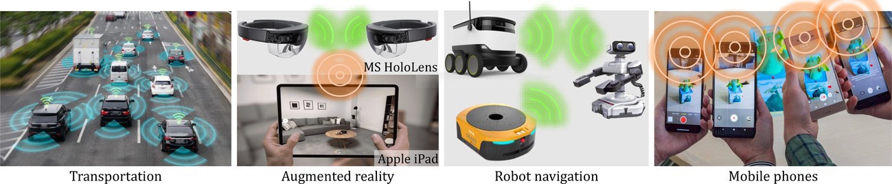
Applications. Due to their low cost, compact form-factors, and low computational complexity, ToF-based active 3D cameras are now the method of choice in most commercial 3D imaging systems, including vehicular LiDARs, and more recently in commodity1,2 and consumer-grade devices such as cell phones, tablets (for example, Apple iPad), gaming and AR/VR headsets (for example, Microsoft Kinect and Hololens). They are also used by inspection and delivery robots to navigate in warehouses24 and perform 3D modeling,9,13 directly impacting safety and functionality. Going forward, our dependence on them is only going to grow as these cameras will drive an even larger, potentially transformative set of applications such as human-machine interaction6 and home robotics.

Active 3D cameras and interference. More generally, ToF cameras belong to the class of active 3D cameras, which consist of a programmable light source that emits spatially or temporally coded light.b For example, the light source could be a laser or an LED whose intensity is modulated over time. The emitted light signal travels to the scene of interest, gets reflected, and is captured by the sensor (typically co-located with the light source), as shown in Figure 2a. Scene depths (and hence, the 3D geometry) are extracted by comparing the emitted and the reflected light. Since the camera actively controls the illumination, they can reliably recover highly precise 3D geometry even in challenging real-world scenarios, including large lighting variations (bright sunlight to dark night sky) and optically uncooperative scenes (shiny materials, textureless and dark objects), which are otherwise difficult to handle for passive 3D cameras.
Although the coded light sources enable high-precision 3D recovery in isolation, multiple active cameras, each emitting their own light signals, can cause mutual interference. In such multi-use scenarios, an active camera’s sensor may receive light emitted not just by its own source, but also by the sources of other cameras. This interfering signal prevents correct 3D depth estimation, resulting in potentially large, systematic depth errors. An example is shown in Figure 2b-f, where the depth of the scene observed by one active camera is significantly distorted in the presence of a second, interfering one. Such errors in the low-level 3D measurements can make it near impossible to extract any actionable information (for example, object detection and recognition, image classification) for downstream machine-learning (ML) algorithms.

Why is now a good time to address multi-camera interference? Until recently, a large proportion of ToF cameras were based on a scanning laser beam that illuminates one (or a few) scene point at a time. Since they illuminate only a small portion of the scene at a time, the probability that two devices illuminate the same point simultaneously is relatively low (Figure 3a). This enabled multiple devices to co-exist without affecting each other. However, they require mechanical moving parts, for example, rotating mirrors, often leading to long acquisition times, high cost, bulkiness, and reliability issues.
To address its limitations, a new emerging class of solid-state ToF cameras flood-illuminate the entire scene (Figure 3b), making them considerably cheaper, smaller, lighter, and faster. Hence, solid-state cameras are fast replacing scanning-based cameras in autonomous driving and robotics applications (Figure 3c). But, there is a trade-off: several active cameras flood-illuminating a scene simultaneously will interfere with each other (Figure 3b). Furthermore, a new generation of consumer devices (e.g., cell phones) with 3D imaging capabilities are becoming ubiquitous. Due to stringent size and cost requirements, these devices also prefer solid-state 3D cameras (Figure 3d), which will create strong multi-camera interference (MCI) whenever multiple active cameras are used in close proximity.
Several active cameras flood-illuminating a scene simultaneously will interfere with each other.
Due to their compatibility with mainstream CMOS fabrication lines, the capabilities of solid-state cameras (spatial resolution, timing precision, signal-to-noise-ratio) continue to grow rapidly.10,33,23 Therefore, these cameras are quickly becoming the method of choice in almost all applications that rely on 3D cameras, including vehicular navigation, robotics, and consumer mobile devices. On the downside, this growth will add to the severity of MCI problems. Imagine several cars equipped with ToF camera-based LiDARs driving in close proximity, or an indoor setting with several consumer devices such as phones and headsets using their 3D cameras simultaneously for augmented reality (AR), localization, or 3D modeling.9,13 It is, therefore, critical to address this problem now so that 3D cameras continue to function reliably across a broad spectrum of real-world scenarios, imaging devices and application domains.
Therefore, as solid-state ToF cameras become ubiquitous in our personal mobile devices, vehicles, homes, and workplaces as well as the basis for numerous critical applications, managing interference across a multitude of these devices will be of profound importance. The goal of this article is to shine a light on this important problem (pun intended) that has received little attention so far: interference of light signals emitted by active cameras and its impact in accurately recovering 3D scene information.
As solid-state ToF cameras become ubiquitous in our personal mobile devices, vehicles, homes, and workplaces, managing interference across a multitude of these devices will be of profound importance.

Can research on wireless interference be used to address MCI? Typical wireless communication systems (for example, Wi-Fi, cellular systems) use radio waves propagating over a shared channel. These systems have dealt with the problem of multi-node interference for many decades. This has led to the development of many techniques using whichever multiple wireless devices can co-exist and communicate over the same shared air medium. Hence, it is natural to evaluate whether strategies developed for mitigating wireless interference can be applied to address MCI. To answer the above question, we first discuss the similarities and differences of how interference manifests in these settings.
At first glance, an active 3D camera is very similar to a wireless transmitter as shown in Figure 4. A wireless transmitter generates radio waves that propagate over the air (usually referred to as the channel/medium) to a wireless receiver located at a distance with a goal of communicating information. The information itself is encoded in the radio waves. An active 3D camera also uses a transmitter and a receiver. The active 3D camera transmitter (or light source) generates a signal (light), and a corresponding receiver (or sensor) captures a reflected instance of this signal. However, unlike the wireless communication systems, the goal of active 3D cameras is to estimate the depth, or distance, of objects in the environment based on the ToF of the received reflected signals. This could be considered as analogous to learning the channel in wireless systems.
The similarities further extend from a single transmitter-receiver (transceiver) pair to a network of transceivers. In a wireless network, when multiple nodes attempt to communicate simultaneously, the radio waves interfere with each other, leading to collisions. Similarly, when multiple light sources flood-illuminate a scene, they collide and corrupt the received signal, resulting in depth errors.
There are, however, two critical differences between these two systems. First, in active 3D cameras, the transmitter and the receiver are co-located, that is, the light source and the sensor are both part of the same active 3D camera (Figure 4b). Second, signals collide in different ways. In a wireless channel, collisions could result in constructive interference or destructive interference, where the signal gets strengthened or weakened. On the other hand, an active 3D camera, modulates the intensity of light, as opposed to the underlying electric field. The key factor to notice is that the intensity of light is always positive with both a constant (DC) and a time-varying (AC) component; the depth is encoded in the time-shift of the AC component. Therefore, the interfering signals from multiple cameras always accumulate additively. Although orthogonal-coding approaches can remove the AC interference, the DC component still accumulates, resulting in higher photon noise.
Despite these differences, we believe that the experiences of the wireless communications and networking community in addressing interference problems can benefit the imaging and computer-vision community in addressing MCI. In particular, we believe that a good understanding of various approaches to mitigating wireless interference and the theoretical foundations and practical considerations of active 3D camera design can together synthesize useful solutions. If successful, the resulting ideas will not just spur widespread adoption of existing technologies, but also enable emerging applications that were hitherto considered impossible. The theoretical tools and techniques developed as part of this work will find applications in a broad range of techniques which involve coded light sources and sensors, such as structured light, tomography, microscopy, as well as optical communication systems using coded light sources.
The experiences of the wireless communications and networking community in addressing interference problems can benefit the imaging and computer-vision community in addressing MCI.
In summary, we answer the question in this subsection affirmatively by indicating that research on wireless interference can be used to address MCI. In the rest of the article, we identify various MCI mitigation approaches by leveraging its similarity to wireless and propose new directions to address the differences between the two scenarios.

Active 3D Cameras: An Overview
An active 3D camera consists of a light source that emits coded illumination toward the scene and a sensor that captures the reflected light, as shown in Figure 2a. The most widely used class of active 3D cameras are based on the ToF principle. ToF-based cameras have a light source which emits temporally coded illumination. For example, the light source could be a laser or a light-emitting diode (LED) that sends out short light pulses or a continuously modulated light. The emitted light travels to the scene of interest and is reflected back to the sensor. The cameras measure the scene depths by measuring the total time of travel, computing the time-shift between the emitted and received waveforms (Figure 5a-b).
ToF-based depth-imaging systems can be broadly classified into direct and indirect ToF systems. A direct ToF (D-ToF) system16,34 estimates scene depths by emitting a short light pulse into the scene and directly measuring the travel time of the reflected pulse (Figure 5a). Most vehicular LiDARs are based on the D-ToF principle. An indirect ToF (I-ToF) system,27,18,11 on the other hand emits light continuously. The intensity of its light source and the exposure of the sensor are both modulated over time for measuring the scene depths. The light-source-modulation and sensor-demodulation functions can be any periodic and continuous functions such as sinusoids, square waves, or trapezoidal functions (Figure 5b).12 I-ToF cameras do not require expensive components, and hence, are routinely used in consumer devices such as Microsoft Kinect and Hololens.
MCI in active 3D cameras. When multiple active 3D cameras illuminate a scene, the reflected signals interfere, corrupting the scene information. In this section, we provide the mathematical background for understanding MCI in active 3D cameras.c
ToF image formation model. The intensity of the light source in a ToF camera is temporally modulated as a continuous periodic function
; it could be a sinusoid,27,18 or an impulse train function.17 The period of typically varies from ns, which corresponds to a measurable distance of m. The light emitted by the source travels to the scene of interest and is reflected back toward the camera. The intensity of the reflected light incident on a sensor pixel is a time-shifted and scaled version of :
(1)
where is the time-shift of the waveform due to travel from the source to the sensor. is the distance between the camera and the scene point imaged at , and is the light speed. is a scene-dependent scale factor that encapsulates the scene’s reflectance properties. The camera computes (typically of the order of ns) by using high-speed, on-chip timing circuits, and the scene distance is estimated as .
Multi-camera interference. If multiple ToF cameras are simultaneously illuminating and imaging a scene point (Figure 2b), the brightness of the light incident at one of the cameras (referred to as the primary camera) is given by:
where is the number of interfering cameras, is the radiance incident at the primary camera due to its own source (Eq. 1), and is the measured intensity due to the source. We drop for brevity. The summation term in Eq. 2 corrupts the true radiance , resulting in erroneous depth estimates. Figure 2c shows an example of a ToF camera using sinusoid modulation. Assuming all the sources use sinusoids (or any other periodic shapes such as squares) of the same frequency, the phase of may differ from the true phase of , resulting in systematic, potentially large depth errors as shown in Figure 2d-f.
Current approaches to addressing MCI. A trivial approach to prevent MCI is to assign different wavelengths to different cameras. This approach only eliminates AC interference, and it faces two practical constraints: (1) the set of available wavelengths is strongly limited by the sensitivity range of the sensor material (typically silicon), as well as the practical requirement for the emitted light to be invisible to humans. This limits the available wavelengths to be
850-950nm, which is the near-infrared region of the EM spectrum; (2) due to laser and sensor hardware constraints, each sensor must be assigned a range of wavelengths (for example, 5-10nm). These constraints restrict the number of distinct wavelength bands preventing assigning a unique set of wavelengths to each active camera. Recent works addressing MCI can be broadly classified into three categories:
Orthogonal coding. The majority of existing works rely on orthogonal coding, such as sinusoids of different modulation frequencies30 or phases,36,20 and pseudo-noise sequences7,8 for different cameras. However, they face challenges similar to frequency division multiple access (FDMA): a limited set of orthogonal frequencies and codes which proves inadequate for the rapidly growing cameras. These approaches often require a central authority that assigns a unique code to each camera, which is not practical.
Time division multiple access (TDMA). Other approaches divide the total capture time of the camera into multiple time slots and assign them to individual cameras randomly.19 These techniques do not scale with the number of interfering cameras.
Mechanical approaches. Another method is to project a planar light sheet which is scanned over the scene. Since only a portion of the scene is illuminated at a time, interference can be reduced.4,35,26 Although these approaches successfully prevent interference, they require mechanical scanning, which increase system cost and size.
Recently, optical phased arrays and micro-electro-mechanical systems (MEMS)-based technologies have attracted attention to resolve the limitations of mechanical approaches. These hardware-based approaches can be integrated into our software/firmware-based approaches to create hybrid approaches to mitigate MCI. However, we focus on wireless-inspired software/firmware approaches to reduce MCI in this paper.

The Promise and Pitfalls of Wireless-Inspired Approaches
Interference is a classical problem in wireless communication. A huge body of literature over multiple decades has examined this problem to enable efficient shared access of a common channel such as the wireless medium. The wireless community commonly refers to these approaches as medium access control (MAC) techniques. Since MCI arises from sharing the common medium, it has similarities to MAC protocols in wireless communication. Here, we showcase the promise and pitfalls of applying well-known wireless MAC protocols to address MCInterference. As previously discussed, orthogonal coding across cameras can only reduce AC interference and not DC interference. A simple solution is to avoid collisions; we adapt a coordinated and distributed collision avoidance from wireless, and simulate them in a multi-camera setting and analyze their performance.
Comparisons using computer simulations of MCI. We developed a physically accurate computational simulator to emulate active 3D cameras, under a wide range of scene configurations and sensor-source parameters. The simulator models different steps of the image formation process as shown in Figure 6. Given a source modulation function , the emitted light is defined as , where is average source power. can be any periodic function. For example, for sinusoid coding, , where is modulation frequency. The light signal received at the sensor is defined as the sum of source reflection at the scene and ambient light:
(3)
where is a scale factor encapsulating scene reflectance and light fall-off, is average ambient power, is scene depth, and is light speed. Noise-free sensor measurement is the correlation between and sensor demodulation :
where is integration time. If we assume sinusoid coding, . Final sensor measurement is obtained by adding photon noise, read noise, and ADC noise to . To recover scene depth, we need multiple sensor measurements obtained by changing the phase of . For a 4-tap sinusoid coding scheme, those measurements are obtained from Eq. 4 with , . The scene distance estimate is obtained by
Using this simulator, we compare the performance of the following two wireless-inspired MCI reduction approaches with the conventional orthogonal coding approach (OCA). We implement OCA by assigning orthogonal modulation frequencies to each camera. The code to simulate MCI reduction approaches is available at https://github.com/purmod/MCI.
CSMA-based MCI mitigation. A popular idea in many communication systems to share a common medium is the “listen before talk” approach. In this approach, interference is potentially mitigated by requiring each transmitter to listen to the channel before transmitting their data. Waiting until the channel is idle ensures that a transmitter does not interfere with an ongoing communication. In wireless parlance, this is called “carrier sensing,” and the technique is often referred to as carrier sense multiple access (CSMA). To ensure no two nodes attempt to transmit simultaneously once the channel is sensed to be idle, CSMA with collision avoidance (CSMA/CA) is widely used in wireless systems such as Wi-Fi. We draw inspiration from CSMA/CA, which requires nodes to wait a random amount of time after the channel is idle before transmitting. Combining carrier sensing and random wait times helps to avoid collisions. In particular, we design a “listen/view before illumination” approach at each camera to avoid interference from other cameras. Before illuminating the scene, if the channel is busy, the camera defers; else, it illuminates the scene and measures the depth information. In our implementation, we divide the total capture time (minimum time to estimate depth) of an active 3D camera into multiple time slots and sense the channel at each slot.
Co-operative random access-based MCI mitigation (CRA). We compare the depth accuracy of CSMA-based MCI with a time-division multiple access (TDMA) approach. If multiple cameras are synchronized to a global clock, their transmissions can be scheduled in fixed slots. Each camera chooses a random sequence of slots to be active and illuminate the scene. In our implementation, all the cameras are synchronized, such that the slot boundaries are the same.

In Figure 7, we compare OCA, CRA, and CSMA in terms of depth accuracy and power consumption as a function of the number of interfering cameras. For depth accuracy comparison at the same source power, we employ depth standard deviation since all compared approaches cause random depth errors due to noise, instead of structured errors. For both CSMA and CRA, we use a slot clash check algorithm19 to check if slot interference occurred, and depth is estimated from the collection of non-clashed slots. Depth standard deviation of each MCI approach is computed from repeated depth estimation. The required power consumption to achieve the same depth standard deviation is also compared. CRA and CSMA, the wireless-inspired approaches, outperform OCA in terms of both depth accuracy and power consumption, as they avoid collisions and hence both AC and DC interference is reduced. Performance improves with the number of cameras, which is desired when active 3D cameras become more prominent in the near future.
Potential pitfalls. Although CRA and CSMA show promising results, the comparisons are based on purely theoretical and idealized simulations. In practice, additional overhead is required to account for various resources, such as power and time for clash check and carrier sensing. Furthermore, adapting wireless-based approaches for MCI has a tradeoff: The probability of collision increases as the network scales; to avoid collisions, more slots should be used, which leads to greater capture time and power consumption. The time to switch from carrier sensing to normal camera mode will further increase slot duration. These can be critical issues for real-time applications, such as vehicular networks. It is also challenging to synchronize multiple cameras to a global clock due to the absence of a central controller. Therefore, to accommodate the constraints of an active 3D camera system, careful algorithm design and post-processing are required. In the next section, we present open research areas that can address MCI using approaches inspired by wireless communication.
The Road Ahead: Challenges in Wireless-Inspired MCI Solutions
We identify the following research directions, each inspired by the rich work on MAC protocols in wireless networks, with open challenges in applying them to active 3D camera networks. We build upon existing approaches to be applied to active 3D cameras by leveraging the opportunities provided by cameras to address their unique constraints.
Distributed interference management. In large-scale active 3D camera networks, resource-efficient, distributed interference-management techniques are necessary. We propose spread spectrum strategies that can estimate ToF from the cumulative reflected signal, enabling multiple cameras to co-exist. Spread spectrum techniques are used to improve a sender’s resilience to interference and enable co-existence with other transmitters by occupying a wider range of frequencies. Since throughput is not a metric of interest in an active 3D camera network, spread spectrum-based approaches are an appropriate choice for MCI.
One of the key opportunities to leverage in active 3D cameras is the co-existence of the transmitter and the receiver; this enables it to maximize the potential of spread spectrum without communication overheads. Most existing active 3D cameras can modulate multiple frequencies to achieve both high precision and large depth range (for example, Microsoft Kinect uses 120MHz, 80MHz and 16MHz25). On the other hand, one of the biggest challenges is the need and ability to cancel background noise. As previously explained, unlike wireless, orthogonal frequencies and codes still contribute to ambient noise in an active 3D camera. A redesign of spread spectrum is needed to address this challenge. We explore two spread spectrum techniques (that are widely used in wireless) and discuss their challenges in applying to MCI.
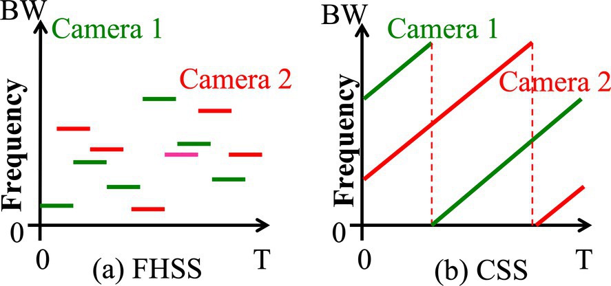
Randomized frequency hopping spread spectrum. Frequency hopping spread spectrum (FHSS) is a spread spectrum technique where the carrier frequency of the transmitter follows a hopping pattern (Figure 8a). Due to its robustness to broadband interference, adaptive FHSS is used in Bluetooth, which enables Bluetooth devices to co-exist with Wi-Fi devices. Bluetooth devices follow a pseudo-random hop sequence to avoid interference, where the hopping pattern is known to the transmitter and the receiver. We adopt FHSS to reduce MCI. In this design, each light source randomly chooses a pseudo-random hopping pattern and hop duration. Since the light source and the sensor are co-located, the hopping pattern is known to both of them. The hopping pattern can also be varied without additional overheads to exchange the hopping pattern. Therefore, the sensor keeps track of ToF of the expected frequencies periodically. The cumulative ToF of the corresponding pattern is then used to estimate the depth of the entire scene.
While FHSS reduces the probability of two cameras colliding in a given slot, unlike RF signals, the intensities of light signals from interfering cameras add up, leading to DC interference even when the hopping patterns of two cameras do not match. With the help of successive interference cancellation, we propose to iteratively cancel DC interference across the frequency bands. For example, consider two cameras using FHSS colliding in three slots. The probability of the two cameras using the same frequencies in the same slots in round two is significantly lower. This probability can be further reduced by increasing the scan duration and introducing empty slots where a light source does not send anything.
Randomized chirp spread spectrum (CSS). Chirp signals have been used for precision ranging in RADAR,15 and more recently, CSS modulation has been used in LoRa21,22 to enable long-range communication. CSS spreads energy by linearly increasing the frequency of operation over time. Since this linear increase makes it robust to interference, it can be leveraged to enable multiple cameras to coexist: Each light source is assigned a unique starting frequency such that the interference from other sources does not affect the AC component of the reflected signal. Figure 8b illustrates a chirp signal transmitted by a source, where the frequency sweeps the entire assigned bandwidth in a given duration.
The probability of collision is inversely proportional to the number of chirps. It is therefore desirable to have a large pool of chirps to reduce collisions. While decreasing step size will increase the number of chirps, the minimum step-size is limited by hardware switching speeds. To address this challenge, non-linear CSS can be explored. A non-linear chirp with initial frequency is similar to that of linear chirp in Figure 8b, whose frequency progression with time is given by a function . By choosing orthogonal non-linear functions, the probability of collisions can be reduced.15,22 Similar to FHSS, CSS also needs to consider DC interference due to cumulative energy from other frequencies. We propose to successively cancel DC interference from one band to another and, leveraging the lack of time synchronization, this offers more possibilities to explore in MCI.
Centralized, networked coordination. While distributed approaches to MCI are necessary for many applications, there are multiple environments that lend themselves well to networked coordination with centralized control. For example, a factory floor with mobile autonomous robots operating in a single administrative domain can easily be coordinated through a central server. In such indoor applications, RF-based wireless connectivity to network devices via a central server that helps with synchronization could be integrated with the cameras. Therefore, combining RF and camera-based networks could offer real-time control of the cameras to a central server. Vehicles with LiDARs on roadways could also accomplish similar goals with roadside infrastructure providing the control function. Finally, home environments are likely the most challenging as there might be multiple environment sensing devices from diverse manufacturers, but if standardization of centralized coordination were to be developed, then all such devices could coordinate through a common hub within the home to manage active camera activities. We propose the following approaches in such centralized coordination scenarios.
Creating a conflict graph in real-time. To schedule simultaneous transmissions in wireless systems, one needs to infer the “conflict graph” that maps the potential of interference between transmitters.28,29,3 Creating such a conflict graph in real time in the active camera domain is more challenging since the goal is to learn the channel. One possible approach is to time-synchronize different light sources and arrange them to send sustained pulses, sometimes in tandem and sometimes in isolation. If there are differences in received outcomes, we may conclude that such transmit-receive pairs interfere. Of course, a challenge lies in achieving various synchronization accuracies. We can combat them by adaptively choosing pulse durations and pulse structures that outlast potential clock synchronization errors. Other sources of inaccuracies can stem with other transmitters in the vicinity that are operating under the control of the centralized coordinator. Time-series analysis to identify and eliminate such interferers is an interesting research problem toward a practical deployment of a centralized coordination. A bigger challenge is the ability to meet the same goals as in a passive setting, that is, by simply observing activities on the channel and using time information to determine the same information. This, however, may be effective if all 3D cameras are sufficiently active. Overall, a hybrid passive-active method would optimize the best of both alternatives.
Networked schedule of activity under centralized control. Prior work on centralized WLANs has shown that it is possible to create efficient partial-traffic scheduling for best performance.31,32 Traffic scheduling is particularly effective when a vast majority of the traffic can be unscheduled, as it can be addressed through simple distributed mechanisms. Centralized control can benefit the fraction that cannot be addressed effectively by those mechanisms. Such traffic scheduling can also be used to minimize collisions in the active camera environments. The real-time conflict graphs discussed previously will inform a centralized coordinator which transmitters might benefit from scheduling while allowing the remaining to be unscheduled. Note that the scheduling requirements might depend on specific environments and the frequency with which transmitters need to rediscover their 3D environment. It also depends on how frequently the environment changes and external, out-of-band information can be used for this purpose. Based on this information, each transmitter-receiver pair that cannot be managed using a distributed approach may be scheduled to time slots to accomplish their scene-sensing goals. Note that a sensing attempt may be scheduled (or not), depending on the other devices attempting to sense concurrently.
Conclusions
We strongly believe that due to their impending growth for consumer applications and their similarities to wireless communications, active 3D camera networks will benefit from new research from wireless experts. In particular, as interference between these cameras grows, sophisticated techniques are needed to handle MCI. Due to some fundamental differences between active cameras and wireless networks identified in this work, careful considerations in designing interference mitigation, cancellation, and coordination approaches are needed. It is interesting to note that some of the early work on interference-mitigation strategies in wireless environments (MACA,14 MACAW5) started by exploring the potential use of wired interference-mitigation strategies in the wireless environment (Ethernet and related CSMA/CD approaches) and their consequent limitations as well as through the process discovering improvements that led to eventually useful solutions. We believe that a similar approach can be taken by using the state-of-the-art wireless protocols as a starting point to uncover how similar strategies can be designed for active 3D camera systems.
We believe this problem domain is ripe for multiple communities to address collaboratively. Successful and effective solutions to this problem can have a big impact in many applications in our homes and society.
Acknowledgments
This research was supported in part by the ONR grant number N00014-16-1-2995, the DARPA REVEAL program, the NSF CAREER Award 1943149, 2142978, the NSF award CNS-2107060, the ECCS 2034415, the U.S. National Science Foundation awards 2003129, 2112562, 2107060, 2212688, and through an award from the U.S. Department of Commerce with award number 70NANB21H043.
Copyright
2023 Copyright is held by the owner/author(s). Publication rights licensed to ACM.


Join the Discussion (0)
Become a Member or Sign In to Post a Comment