Abstract
Radar sensors have recently been explored in the industrial and consumer Internet of Things (IoT). However, such applications often require self-sustainable or untethered operations, which are at odds with the high power consumption of radar. This paper proposes NeuroRadar, a neuromorphic radar sensor, to achieve low-power wireless sensing. Neuro-Radar jointly optimizes the analog hardware and the computation model to mimic the highly efficient biological sensing and neural-processing systems. NeuroRadar features a highly simplified radar front end, which eliminates the power-hungry components in conventional radars. It directly “encodes” ambient motion into spiking signals, which can be processed using spiking neural networks running on energy-efficient neuromorphic computing platforms. We have prototyped NeuroRadar and evaluated its performance in two use cases: gesture sensing and localization. Our experiments demonstrate that NeuroRadar can achieve high sensing accuracy at orders of magnitude lower power consumption compared with traditional radar.
Radar sensors in Internet of Things (IoT) systems have gained traction in recent years and are widely used in healthcare, smart homes, industrial automation, and intelligent transportation. The high power consumption of radar hardware remains a significant challenge, particularly for battery-operated IoT devices and wearables, where energy efficiency and battery lifespan are crucial. Compounding this issue, numerous smart-sensing applications—such as motion-activated security radar, wearable gesture recognition, and activity classification—often employ power-intensive artificial neural networks (ANNs) for signal processing. Unlike human neurons that operate in short, pulse-based bursts, ANNs prolong the activity of their “neurons” using continuous activation functions, which substantially increases the power demands of IoT devices. Furthermore, ANNs use the classical von Neumann architecture, which frequently shuttles data between physically separate CPU and memory units, resulting in additional processing overhead.
Recent advances in neuromorphic engineering have inspired spiking neural networks (SNNs) and dedicated neuromorphic circuits8 that better approach the efficiency of sensory signal processing in the brain. SNNs are structured to mirror the pulse-based behavior of the human nervous system. They consist of spiking neurons and the synaptic connections between them. Realized on dedicated neuromorphic circuits, SNNs showcase exceptional energy efficiency that surpasses traditional von Neumann computing units by orders of magnitude.4 The revolution in neuromorphic computing has also given rise to state-of-the-art neuromorphic sensing hardware, such as the energy-efficient, fast-response event camera.11
Inspired by these advances, recent research has proposed SNN-based signal processing to facilitate low-power radar operation.2,3 However, these systems do not incorporate a full-fledged neuromorphic hardware architecture. Primarily, the analog front end of these SNN radar systems2,3 remains the same as traditional radars. Although SNN-based signal processing has lowered signal-processing power consumption to the order of hundreds of µW2, the radar front end can demand tens to hundreds of milliwatts. This discrepancy poses a challenge to achieving truly energy-efficient radar sensing. Additionally, SNN radar systems2,3 continue to rely on conventional CPUs or digital signal processing (DSP) units for signal processing. The radar signals must be first sampled by analog-to-digital converters (ADCs), mapped into spikes, and then processed by SNNs for ranging or environmental perception. Unfortunately, the extra sampling steps prior to the SNN involve traditional computing units, which adds a substantial overhead, underutilizing neuromorphic computing’s full potential.
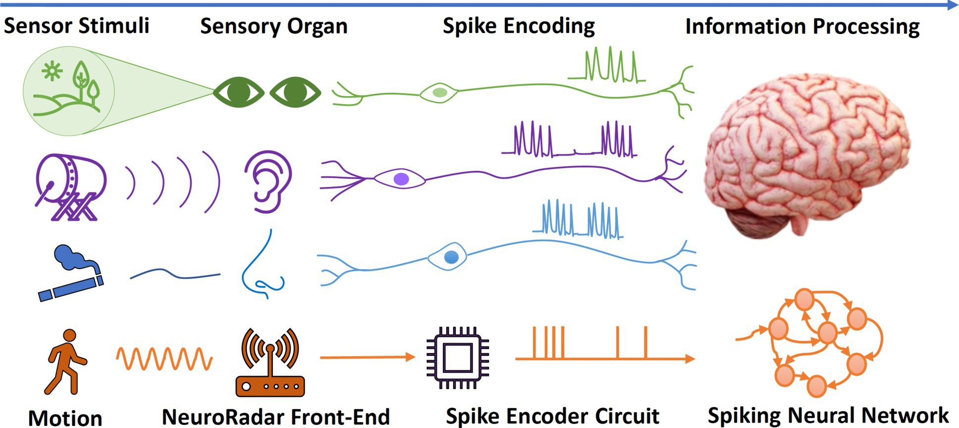
In this paper, we introduce NeuroRadar, a novel low-power radar-sensing system that fully exploits the power of neuromorphic sensing and computing. NeuroRadar draws inspiration from neuromorphic sensors that mimic mammalian sensory systems, generating event-triggered outputs in response to external stimuli, as depicted in Figure 1. Contrary to traditional radars with continuous frame-based outputs, NeuroRadar produces spiking patterns upon detecting motion in the surrounding area. Unlike the recently proposed SNN radars,2,3 NeuroRadar follows a neuromorphic architecture that jointly designs the analog sensing front end and spiking signal processing:
SIL-based radar sensor front end. NeuroRadar employs a drastically simplified RF front end that removes most power-intensive active RF components that exist in traditional radars, leaving only a low-power free-running oscillator. NeuroRadar senses environmental changes using the self-injection locking (SIL) principle,2,3 where the oscillator’s frequency is influenced by motion in the surrounding area. However, a single SIL sensor cannot provide angular resolution and accurate range information, as it only senses environmental motion information. Thus, we further propose to employ an array of SIL sensors with judiciously separated carrier frequencies. With the SIL sensor array, NeuroRadar can implicitly encode spatial information through the multi-channel spiking signals, which can subsequently be decoded using application-specific SNN models.
Analog spike encoding and full SNN processing. NeuroRadar converts ambient motion signals from the sensor front end into spikes using an analog spike-encoding circuit. The spike encoder follows a biological neuron model, preserving all the essential sensing information in the spike sequences. The spike sequences can then be directly processed by the SNNs on neuromorphic computing systems, thereby eliminating the need for any non-spike-based computing units. Consequently, we can train the SNNs using these raw spike signals for various tasks, including gesture recognition and localization. This comprehensive SNN processing workflow allows NeuroRadar to deliver application-specific sensing results with superior energy efficiency.
To verify the effectiveness of our design, we prototype NeuroRadar using discrete RF circuits and further perform simulation for the integrated circuit (IC) version. Our experiments show that a single-RF-chain NeuroRadar can effectively sense motion in the environment while consuming only 780µW power (IC: 240µW), which is one to two orders of magnitude lower than existing continuous-wave (CW) radar systems with similar operating frequencies. We further conduct two case studies to verify the usability of NeuroRadar for practical IoT sensing applications. Specifically, NeuroRadar can facilitate hand-gesture recognition with an accuracy of 94.6% and perform moving-target localization with an average error of 0.98m. Compared with other SNN-based gesture-recognition systems2,3 with similar capability, NeuroRadar saves 78% to 93% computing power. NeuroRadar reduces end-to-end power consumption by one to two orders of magnitude for both use cases, compared with existing radars. Considering the spatial-resolution and motion-detection capabilities, NeuroRadar can potentially be used in a wide range of wireless IoT sensing applications, such as vital sign sensing, surveillance alarm, and more.
In summary, we make the following contributions:
We introduce NeuroRadar, a novel low-power radar paradigm that realizes the concept of neuromorphic radar sensing. NeuroRadar incorporates a spike-generation radar sensor that directly interfaces with SNN-based neuromorphic processors, leading to superior energy efficiency.
We devise a low-power, low-complexity radar front end based on the SIL principle. Both our theoretical analysis and experimental results demonstrate that multi-chain SIL radar sensors can supply ample information for short-range, low-velocity sensing applications.
We implement the neuromorphic radar system through a printed-circuit board (PCB) prototype and carry out simulations for the IC version. Our experiments verify NeuroRadar’s ability to empower resource-constrained IoT devices to perform low-power smart sensing.
Background
Self-injection locking. Injection locking is a phenomenon where an oscillator’s frequency is locked to the frequency of an external injection signal, while self-injection locking7 is a special case where an oscillator’s frequency is affected by a reflected version of its own signal, as depicted in Figure 2.
Based on classical analysis of injection locking,14 we can model the frequency shift of the oscillator caused by the reflectors in the environment:
(1)Here, is the center frequency of the oscillator, is the quality factor of the LC resonating tank, is the injection signal from the reflector, is the oscillator signal, is the distance of the reflector, is the speed of light, and is the total number of reflectors. Notably, the strength of the reflected signal, , is proportional to . Its phase, , encapsulated in the sine term, is also related to . Thus, the oscillation frequency is modulated by the motion of the reflectors.
Spiking neural networks. Biological neurons communicate by generating and propagating electrical pulses or spikes. Neurons are interconnected via specialized junctions termed synapses. A neuron fires a spike whenever enough incoming pulses accumulate to push its membrane potential above a certain threshold, following which the neuron resets itself. This process is often abstracted as leaky-integrate-and-fire (LIF).9 In traditional ANNs, neurons encode information in a complex network of real-valued activations. Activation functions such as ReLU essentially approximate the spiking rates of biological neurons. In contrast, SNNs mimic the human neuron system more closely by using spiking signals directly for inter-neuronal communication and using the timing rather than shape of spikes to convey neural information.
The computation and energy-efficiency advantages of SNNs originate from two fundamental aspects. First, the neuromorphic architecture can realize massive parallel processing, since each neuron represents an integrated memory and computation unit, in contrast to the rigid separation of CPU and RAM in von Neumann architectures. Thus, SNNs can potentially continue to push the intelligence per Joule as Moore’s law scaling comes to an imminent end. Secondly, the energy consumption of SNNs is proportional to the number of processed spikes, with each spike requiring as little as a few picoJoules.4 As information is sparsely encoded in the rates/timing of the spiking neurons, a SNN can implement the same end-to-end functionality as an ANN but with much lower energy expenditure.
Notably, the advantages of SNNs can be manifested only on specialized non-von Neumann in-memory computing platforms specifically designed to process spiking inputs, such as Intel Loihi.8 Albeit an active area of research, neuromorphic computers have already demonstrated orders of magnitude of energy efficiency than conventional computing architectures.4
System Overview
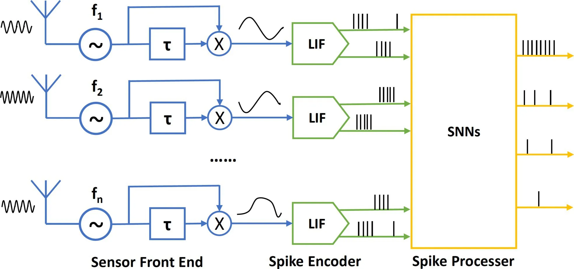
NeuroRadar consists of three main components: sensor front end, spike encoders, and spike processors (Figure 3). The sensor front end senses ambient motion, and the output signals are converted into spike sequences (referred to as spike trains) by the spike encoders. These spike trains are then directly processed by the energy-efficient SNNs.
Sensor front end. The NeuroRadar front end emits a weak, CW single-tone signal in the 0.3∼3GHz ultra-high frequency (UHF) band. The core component is a self-injection locked oscillator (SILO) whose frequency is modulated by the motion of the surrounding targets.23 By demodulating this frequency shift, the system generates a baseband signal that carries the motion information. We further introduce a sensor-array design that combines multiple SILOs with different operating frequencies to provide richer spatiotemporal information.
Spike encoder. The spike-encoding circuit takes the baseband signal produced by the front end and converts the signal into spike trains following the LIF model.9 Given that the input is AC-coupled and the signal comprises both positive and negative parts, two spike encoders are jointly employed to encode each channel of the radar sensor. The spike-encoding circuits operate entirely in an event-driven manner; they only generate spikes when the sensor front end detects motion and stays idle otherwise.
Spike processor. The spike encoders interface directly with the neuromorphic computing circuits, enabling all signals to be processed within the spike domain. Our approach involves designing multi-layer convolutional SNNs to process the multi-channel spike chains from the NeuroRadar sensor array. These SNNs execute pattern recognition and regression tasks according to the application requirements.
Sensor Front-End Design
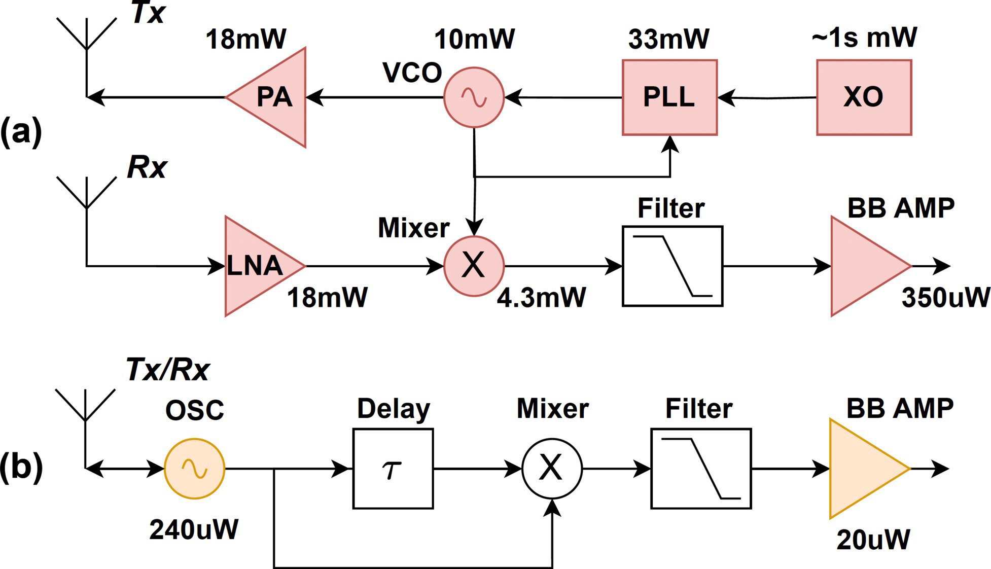
Design principle. The main principle of the front-end design is to reduce power consumption for NeuroRadar. To achieve this, we first analyze the power-hungry RF components of traditional radars that lead to high power consumption. A typical CW radar front end, as shown in Figure 4a, includes elements such as a voltage-controlled oscillator (VCO), phase-locked-loop (PLL), crystal oscillator (XO), mixer, low-noise amplifier (LNA), and power amplifier (PA). While power consumption can vary depending on specific designs, we annotate a representative CW radar22 for reference. These active RF components are necessary to maintain the high sensing performance required for advanced applications, such as automotive perception. Such high-profile radar front ends require a high power budget of several hundred milliwatts, irrespective of the signal-processing hardware.
In contrast to traditional radar systems, neuromorphic systems exhibit superior power efficiency and rapid response times by emulating the event-driven communication and computation in biological neural systems.5 Event cameras,11 also known as dynamic vision sensors, represent an epitome of neuromorphic sensing systems. Instead of capturing full frames at a fixed rate, event cameras generate asynchronous events in response to changes in pixel-level brightness. This event-driven approach increases the camera’s dynamic range while substantially reducing power consumption and data processing load.11
Inspired by the event camera, we design a NeuroRadar sensor front end that only responds to changes in the radar channel (caused by motion) and produces asynchronous spike signals that contain relevant motion information. To attain these properties, we extend the SIL structure and develop spike encoders to convert radar signals into spike trains. A SIL radar is inherently a motion detector, which aligns well with the event-driven neuromorphic sensing principle. Moreover, SIL radars feature a simplified architecture, which makes them power-efficient and cost-effective to implement.
SIL sensor design. SIL radar adopts a simplistic architecture with only three RF components: an oscillator, a time delay unit, and a mixer (Figure 4b). The oscillator emits an RF signal that becomes self-injection-locked due to environmental reflections. A time-delay unit and mixer demodulate the frequency shift caused by moving targets. The system’s total power consumption is kept under 300µW with optimized design.
While the removal of active RF components such as LNA or PA typically results in low sensitivity, the SIL radar’s unique architecture provides a sensitivity gain that compensates for the impact. A target’s motion induces phase modulation on conventional a Doppler radar, in contrast to frequency modulation on the SIL radar.23 The demodulation circuit extracts the phase change over the delay time . As phase is the time integral of frequency, SIL radar’s demodulation process inherently integrates and enhances the motion signal. Following the empirical model in Tang et al.,20 we find that the SIL radar can provide a sensitivity gain of around 19.97dB with = 80ns and carrier frequency 915MHz (corresponding to our implementation), which can be traded for low-power operations.
This property ensures that despite the simplified design, a SIL radar can still support our targeted IoT sensing applications that require only limited range/velocity resolution (for example, occupancy detection, coarse indoor tracking, and hand-gesture recognition).
Array of SIL sensors.
Sensing information from a single SIL radar. Suppose a target is moving randomly within the surrounding area and a continuous frequency shift (Eq. 1) of the oscillator is observed. The demodulation circuit turns the frequency shift into a continuous voltage signal y(t), and from Eq. 1:
(2)Here represents an abstracted gain encapsulating various factors (that is, demodulation gain, antenna gain, and any practical system loss), and σ is the radar cross section (RCS) of the target, which is an unknown parameter and may fluctuate over time.
The range information is embedded in both and , but this alone is insufficient for localizing the target. Although includes absolute range information, it cannot be estimated due to the unknown target RCS σ. Additionally, as is 2π−periodic, it only contains ambiguous range information. Moreover, a single sensor fails to provide the angular information of the target. This implies that given a distance r, the actual location of the target could be anywhere on a circle with a radius of r. Therefore, further information is required to precisely localize the target.
Frequency-diverse SIL sensor-array design. To overcome the lack of range/angle resolution, NeuroRadar combines multiple SIL radar sensors operating at different frequencies, forming a frequency-diverse array (FDA). A colocated sensor array can infer the direction of the target by exploiting the phase difference of the received signals across the sensors, whereas the frequency diversity offers the potential to resolve the range ambiguity.
To quantify the sensing capability of the array design, we derive a model-driven localization and speed-estimation process. Consider a linear array of K sensors, where the position and frequency of the k-th sensor are and , respectively. Since NeuroRadar only detects motion, we suppose a target moves at a constant speed within a short time (for example, 0.5s), and a total of M observations are made with an interval of ∆t. According to Eq. 2, when a target is located at and moves with velocity , the theoretical observation vector:
(3)where is the distance between the target’s location at time m∆t and the k-th radar sensor at . In the model, the amplitude is not considered because, in practice, it fluctuates randomly due to the time-varying RCS and provides unreliable information.
Given the real observation vector from the radar sensor array, the location and speed of the target can be estimated by
(4)Here, computes the correlation between the real observation vector and the theoretical observation vector.
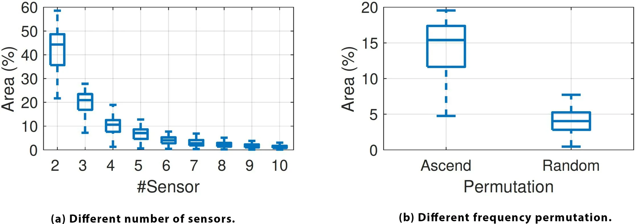
To establish the optimal number of radar sensors required to achieve reasonable resolution, we use the above model to numerically derive the sensing resolution. In the numerical simulation, the sensor operating frequencies are set between 800MHz and 950MHz. The simulation considers targets ranging from 0.5m to 7m and sensing directions between 45°and 135°relative to the sensor array. Target speeds range from 0.5m/s to 3m/s, with their moving directions varying between 0°and 360°. We randomly sample 100 targets and calculate the average percentage of the area with a correlation value (Eq. 4) exceeding –3dB. This area represents the ambiguity of NeuroRadar.
The results depicted in Figure 5a reveal that the ambiguous area decreases as the number of sensors increases. A smaller ambiguous area signifies a reduction in ambiguous side lobes and a more concentrated main lobe. The empirical findings suggest that an array of six sensors is sufficient for NeuroRadar to resolve most targets, striking an effective balance between resolution and array size.
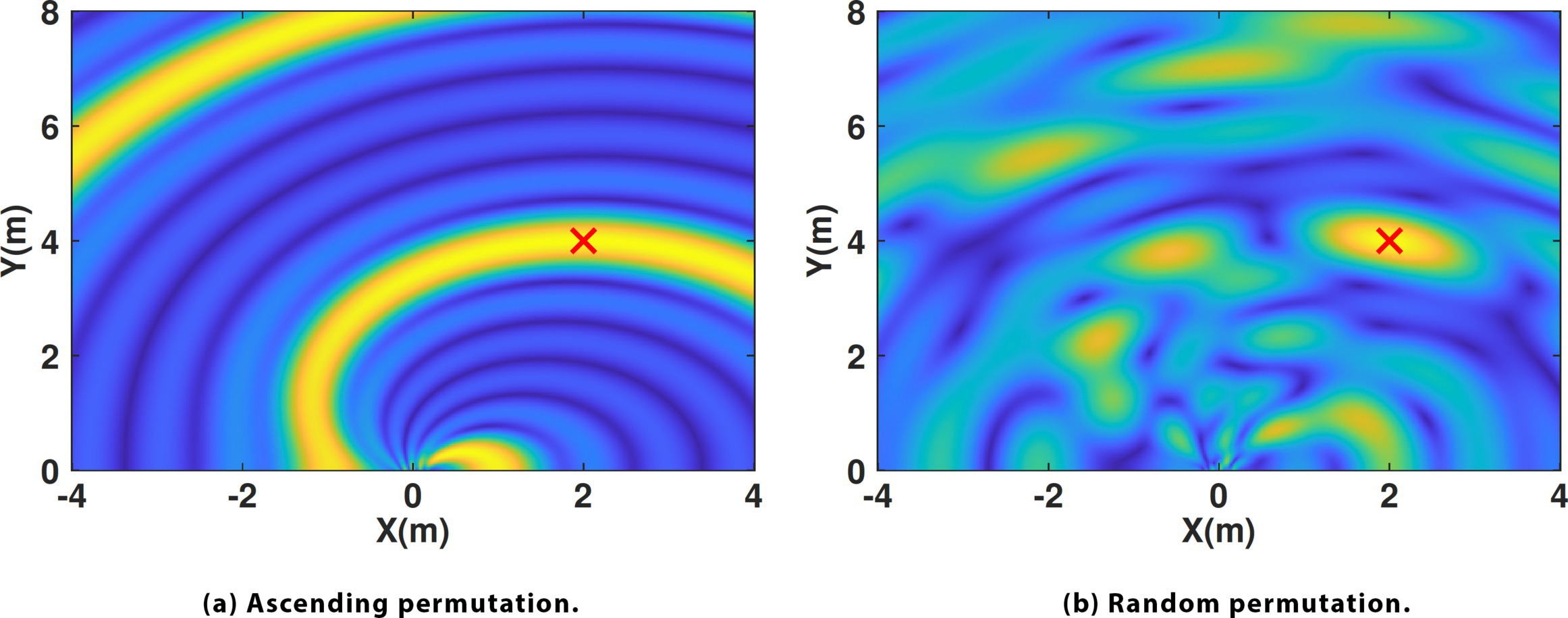
The configuration of frequencies in the sensor array impacts sensing ambiguity. As shown in Figure 5b, a random frequency permutation results in a significantly smaller ambiguous area compared to an ascending permutation. Figure 6 presents the location ambiguity area given an observation vector from a target at a specific location. Consequently, NeuroRadar takes advantage of this property by adopting a random frequency permutation for its sensor array.
Spike Encoding and Processing
Spike encoder design. To facilitate end-to-end SNN signal processing, NeuroRadar employs an analog spike-encoding circuit to directly transform the SIL radar signals into spike trains. The spike encoder must preserve the essential sensing information in Eq. 2. To this end, the encoder should perform spike-rate encoding, in which the firing frequency increases linearly with the amplitude of the input signal. As a result, the phase information in Eq. 2 is represented as variations in spike density.
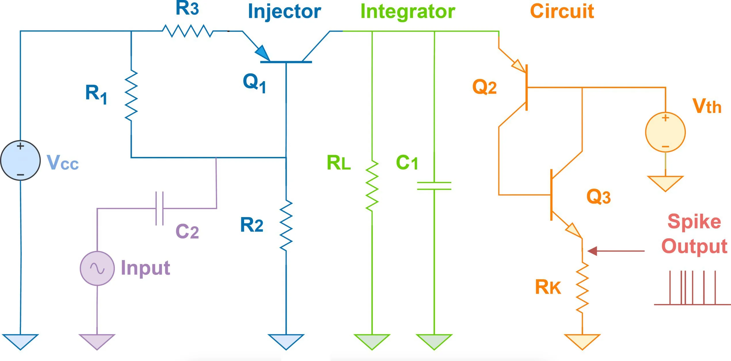
We design our spike encoder based on the aforementioned LIF neuron model.9 The LIF neuron model consists of a current injector, an RC parallel circuit, and a spike firing circuit, as depicted in Figure 7a. In the human nervous system, a neuron’s membrane potential u(t) rises upon receiving input stimuli I(t) from other neurons. Once u(t) reaches a threshold uf, the neuron triggers a spike to adjacent neurons and resets its voltage to a resting value ur, as shown in Figure 7b. In the absence of input, the membrane potential decays exponentially to its resting value through a leaky resistance path.
The spike firing rate can be determined by the membrane time constant , with being the membrane capacitance and representing the leaky resistance. Given a constant input I0 from the SIL radar, the spike firing interval can be written as9:
(5)When the leaky resistor is large, the spike firing rate , which grows linearly with the input signal.
SNN design. As the motion signals are converted into multiple parallel spike trains, we design SNNs to process the spiking signals and extract the spatiotemporal features. The overall structure of the SNN includes three main components: spike buffering units, convolution layers, and spike decoders (Figure 8).
Spike buffering units. The input spike sequences initially arrive at the spike buffering units, which are made up of cascaded time-delay units. Each delay unit imposes a consistent time delay of ndly clock ticks, and the output spikes then enter the next-stage time-delay unit. In most neuromorphic computing hardware, SNNs are realized using digital circuits, with neuron states being updated synchronously according to a clock tick (for example, 1ms). Upon completion of the input sequence, the spike buffering units concatenate the outputs from all delay units and present the spikes concurrently to the subsequent layer. To improve the performance of the SNN, the buffered spikes are repetitively dispatched to the next layer every nint clock ticks. By flattening the temporal dimension of the spike sequence, the spike buffering units simplify the task for the subsequent convolution layers in extracting the temporal features of the spike sequence.
Convolution layers. Convolution layers are essential components of convolutional neural networks (CNNs), which can detect local spatial patterns and structures within an image. With the spike buffering units flattening the temporal dimension of the input spike sequences, convolution layers can be similarly employed to extract the spatiotemporal features of the spike sequences. Consequently, we design a stack of convolution layers, accompanied by other layer types, such as pooling layers and fully connected layers, to process and classify the extracted features.
Spike decoders. In NeuroRadar, the SNNs are trained in such a way that the output values are represented by the spike firing rate of neurons in the final layer. Eventually, the output spike rate must be converted into a continuous value that can be interpreted by the sensing applications. For classification tasks, the prediction probability for each class can be determined by applying low-pass filtering to the spikes from each output neuron representing the respective classes. For regression tasks, the output values are represented by an ensemble of neurons. We train decoders to perform a linear mapping between the neuron outputs and the final output following Stewart.19
SNN training. SNN training is crucial for extracting spatiotemporal features from input data. In NeuroRadar, the trainable parts of the SNNs are the convolution layers and the spike decoders. The ANN-SNN conversion method,16 which is employed for training the SNNs in NeuroRadar, involves training a traditional ANN with the same structure as the desired SNN. We employ traditional neuron models, such as ReLU neurons, and conventional back-propagation algorithms to optimize the connection weights within the ANN. After training, all the ReLU neurons in the ANN are replaced with spiking neuron models, specifically LIF neurons. Lastly, weight scaling needs to be performed for the SNN to ensure a reasonable spike firing frequency. After completing these steps, the trained ANN is effectively converted into a SNN, which can then process spike input efficiently and accurately.
System Implementation
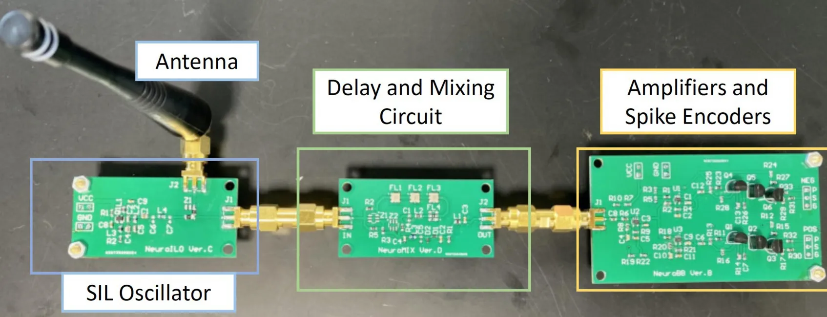
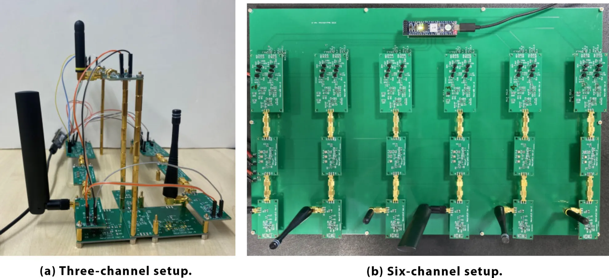
We build a NeuroRadar hardware prototype using discrete components on PCBs, which comprises up to six SIL radar channels with different operating frequencies. Ideally, for a real neuromorphic system, the spike encoders should directly interface with neuromorphic computing hardware and send spikes to a pre-trained SNN as input. However, due to a lack of highly specialized neuromorphic processors, we implement the SNN using simulation frameworks that are well-established in the neuromorphic computing research community. Specifically, we adopt the Nengo-DL framework13 because it supports deep SNN training and accurate emulation of real neuromorphic computing hardware such as Loihi.8 In addition, due to the need for offline SNN training on the simulated neuromorphic computer, we still need to sample the spikes digitally using an FPGA and store the timestamps on a host PC.
Self-injection locked oscillator. Our SILO prototype employs a Clapp oscillator built using an RF transistor along with discrete LCR components. The output power of this oscillator design is approximately –20 dBm, and a monopole antenna is used for RF signal transmission.
Time delay unit. NeuroRadar requires a time delay to demodulate the motion signal (Sec. 4.2). A longer delay with minimal insertion loss is desired to attain a large demodulation gain, so the goal is to maximize the gain delay product. We choose to use surface acoustic wave (SAW) filters to implement the time delay because of their compact size, low attenuation (1–2dB), and reasonable delay time (tens of nanoseconds). In the actual implementation, we cascade three to four SAW filters to achieve a stronger baseband signal.
Low-drive mixer. The mixer multiplies the oscillator signal with its delayed replica and extracts the frequency shift during the time delay. For power efficiency, we opt for passive diode mixers (Infineon BAT63) which, in principle, exploit the nonlinearity of diodes to achieve signal mixing. Further, an impedance-matching circuit preceding the mixer is designed to maximize power delivery from the SILO, and a low-pass filter following the mixer is employed to attenuate high-frequency signals.
Spike encoding and sampling. We design spike-encoder circuits to emulate a LIF neuron, following the description in Section 5.1 and Figure 10. To provide spike samples for the Nengo-DL emulation, we connect all output channels of the spike encoder to a lightweight FPGA, Xilinx CMOD-A7, for sampling. The FPGA samples the spike sequences by polling the digital I/Os. Whenever a spike is detected, each sampling channel creates a frame that contains the timestamp of the spike and the channel index. The frames are sent to the host PC using a universal asynchronous receiver/transmitter (UART) block.
Evaluation
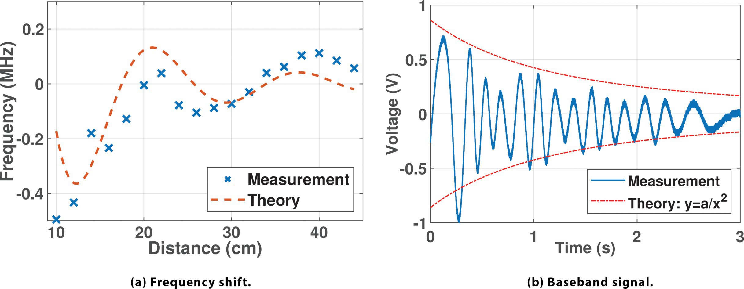
Microbenchmark of the SIL oscillator. We carry out experiments in a multipath-rich lab setting to assess the motion modulation capability of the self-injection oscillator. To control the experimental conditions, we use a 20×20cm aluminum sheet as a representative target, place it at predefined locations, and measure the SILO’s frequency using a spectrum analyzer. As Figure 11a illustrates, the measured frequency shift aligns closely with the theoretical pattern described by Eq. 1. These results indicate that the frequency of the SILO can indeed be effectively modulated by the movement of nearby reflectors, and the frequency shift pattern is not affected by the presence of multipath clutter.
Microbenchmark of the motion demodulation circuit. We proceed to validate the motion demodulation circuit by attaching it to a running SILO. A target (an adult) moves away from the radar at an approximately constant speed from 0.5m to 3m. Figure 11b shows the demodulated signal, which follows the sinusoid pattern consistent with Eq. 2. As the target moves away, the reflected signal becomes weaker, causing less frequency variation in the oscillator. The overall baseband signal strength decays approximately proportionally to 1/r2. In addition, it can be estimated that the distance the target covers (close to the ground truth of 2.5 m), where n = 14 is the completed cycles, and the wavelength λ = 37.2 cm. Therefore, the result shows that the motion demodulation circuit can effectively convert the frequency shift of the oscillator into a continuous baseband signal.
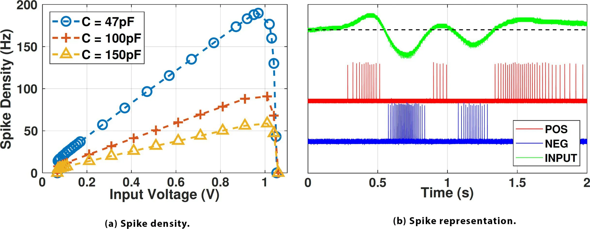
Spike encoder properties. We profile the spike-encoding circuit by applying different DC voltage levels at the input and changing the membrane capacitance (Section 5.1). Figure 12a shows the spike density with respect to the input voltage. As analyzed, the spike firing rate can be increased with smaller membrane capacitance. From Vin = 0 to 0.07V, the spike encoder is in the dead zone and produces no spikes. When 0.07V < vin < 0.90V, the spike firing rate increases approximately linearly with the input voltage, as delineated in Eq. 5. When vin > 0.90V, the spike rate starts dropping quickly down to 0. The spike density plot shows that the spike encoding circuit achieves a one-on-one mapping between the input voltage and spike density. We then connect a real baseband signal from the motion demodulation circuit into the spike encoders and convert it to spike trains. Figure 12b shows the spike representation of the signal. We find that the spike generation is indeed event-driven and asynchronous, as no spike is generated when the input is 0V, and the spikes can be fired at any random time without any explicit synchronization signal.
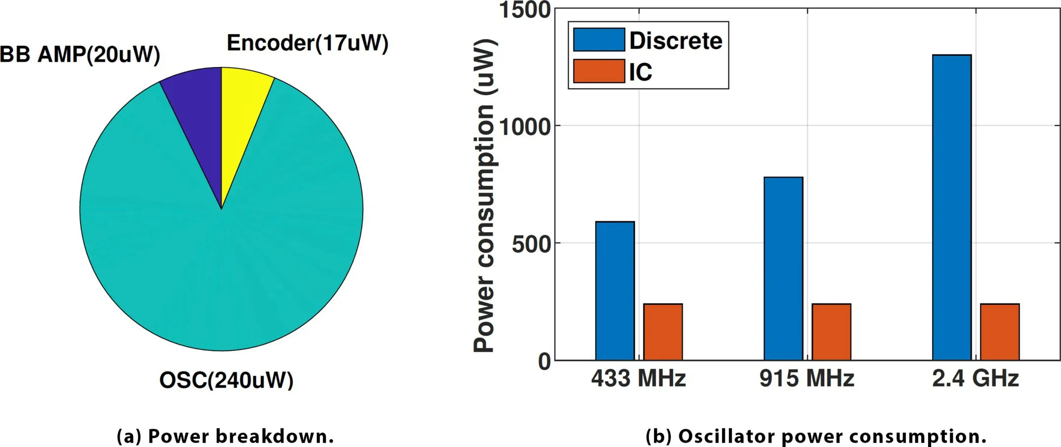
Power consumption of the front end. Next, we characterize the power consumption of a single-channel SIL radar. The radar front end comprises three main parts: the oscillator, the baseband amplifier, and the spike encoder. As shown in Figure 13a, the system’s power consumption is dominated by the oscillator, which is the sole active RF component in the system. Due to the low signal bandwidth, the baseband amplifier can be designed with low power consumption, consuming merely 20µW power. The power consumption of the spike encoder is primarily due to the quiescent current induced by resistor dividers that are used to provide a DC bias. Each spike generation only consumes around 90pJ and therefore has a negligible impact on the total power consumption. Figure 13b shows the power consumption of the oscillator at popular operating frequencies in the UHF band. The IC version, which adopts a more power-efficient oscillator structure (discussed in Section 6), consumes less power than the discrete version. The total power consumption of the radar front end falls below 300µW, underscoring NeuroRadar’s low-power operational capacity across different operating frequencies in the UHF band.
Case Studies
In this section, we implement and evaluate two use cases based on NeuroRadar: hand-gesture recognition and moving-target localization (Table 1). For each case, we train and test the SNN, collect spike chain data, and use them to drive the neuromorphic processor emulation in the NengoDL.13 We assume that all the SNNs in our comparisons run on the Intel Loihi neuromorphic chip and the energy consumption data can be found accordingly.8
| Type | Dimension | Channels | Kernel | Stride | Pool | |
|---|---|---|---|---|---|---|
| 1 | Conv. | 6 250 | 1 | 1 16 | 1 4 | 1 1 |
| 2 | Conv. | 6 59 | 32 | 3 16 | 1 2 | 1 1 |
| 3 | Conv. | 4 22 | 32 | 4 8 | 1 1 | 1 1 |
| 4 | dense | 1 15 | 48 | N/A | N/A | N/A |
| 5 | dense | 180 | N/A | N/A | N/A | N/A |
| 6 | dense | 12 | N/A | N/A | N/A | N/A |
Gesture recognition. We customize NeuroRadar for hand-gesture recognition with three SIL channels with distinct frequencies around the 866/915MHz band. We define a set of 12 gestures, as shown in Figure 15. In the gesture set, hand-movement direction is diverse within a 3D space (for example, push, pull, left, right, up, and down), and some gestures require two hands to move simultaneously.
The three-channel version is employed to recognize all 12 gestures. In the setup, two antennas are placed on a horizontal line, with a spacing of λ/4, with λ being the average carrier wavelength. The third antenna is placed above the horizontal line and forms an equilateral triangle with the other two antennas, as shown in Fig. 14a. The gestures are made in front of the antenna plane, facing the center of the triangle. The spacing is designed to be comparable to the displacement of a hand when making gestures, affording more distinguishable signal patterns. The elevated antenna provides richer information for vertical hand movement (such as “swipe up” or “swipe down”).
As each SIL radar channel is paired with two spike encoders (Section 6), the three-channel setup produces six spike sequences, and the timestamps of the spikes are recorded for SNN training. Each gesture sample contains sequences of spikes across a time length of 1.5s. As explained in Section 5.2, we set ndly = 6 (6ms), which results in an input dimension of 6 × 250 for the three-channel setup (Section 5.2). In total, we collected 2,400 samples, 200 for each gesture. We divide the samples into a training set (1,920 samples) and a test set (480 samples) with a random 80/20 split.
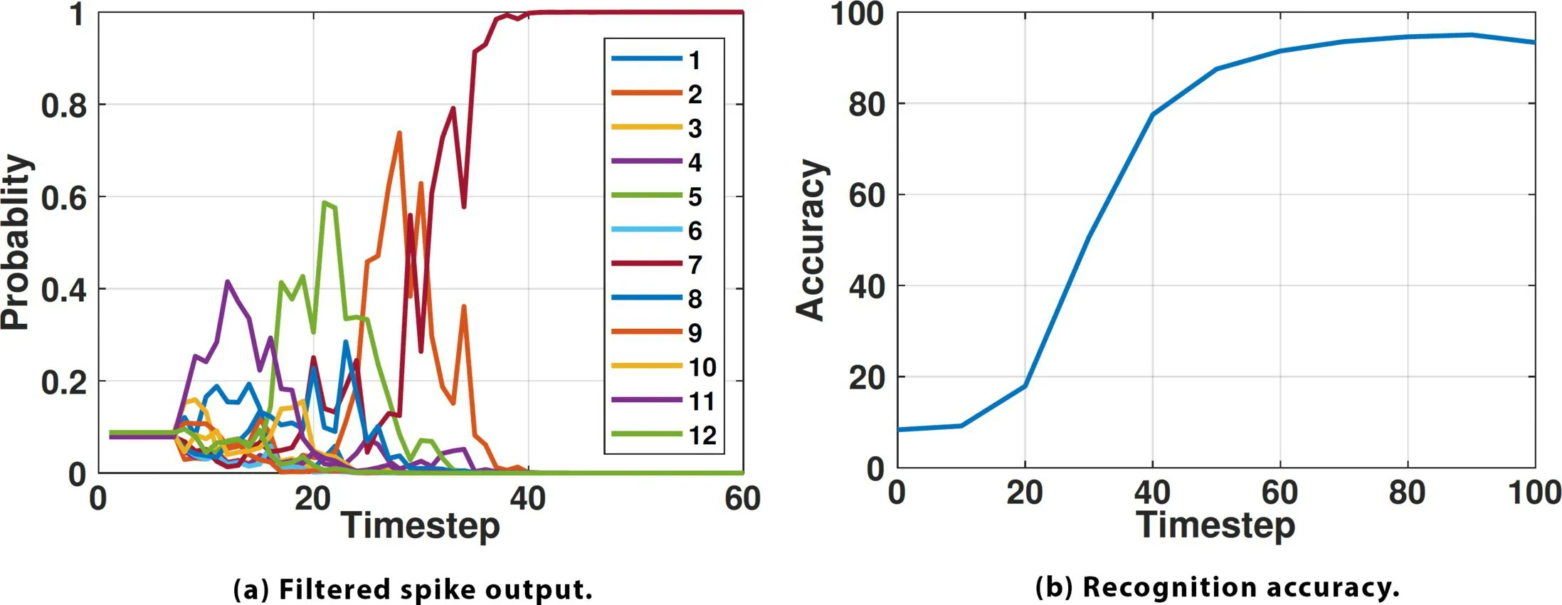
Figure 16 summarizes the gesture recognition outcome. As shown in Figure 16a, the filtered spike signal at each output neuron is interpreted as the probability of each class, and it needs sufficient time-steps to stabilize. Figure 16b indicates that the SNN needs approximately 80 time-steps to produce recognition results with an accuracy exceeding 90%. This means that after gesture operation input is complete, the SNN needs a mere 80ms to produce a reliable result, which is sufficient for most applications. The confusion matrix in Table 2 shows that NeuroRadar can distinguish 12 different gestures, with gesture #10 slightly less accurate than the others.
| 1 | 2 | 3 | 4 | 5 | 6 | 7 | 8 | 9 | 10 | 11 | 12 | |
|---|---|---|---|---|---|---|---|---|---|---|---|---|
| 1 | 0.94 | 0 | 0 | 0 | 0 | 0 | 0 | 0 | 0.03 | 0 | 0 | 0.03 |
| 2 | 0 | 0.95 | 0 | 0 | 0 | 0 | 0 | 0 | 0 | 0 | 0 | 0.05 |
| 3 | 0 | 0 | 0.93 | 0 | 0 | 0 | 0 | 0.02 | 0.05 | 0 | 0 | 0 |
| 4 | 0 | 0.03 | 0 | 0.91 | 0 | 0 | 0 | 0.03 | 0 | 0 | 0 | 0.03 |
| 5 | 0 | 0 | 0 | 0 | 0.97 | 0 | 0 | 0 | 0.03 | 0 | 0 | 0 |
| 6 | 0 | 0.04 | 0 | 0 | 0 | 0.96 | 0 | 0 | 0 | 0 | 0 | 0 |
| 7 | 0 | 0 | 0 | 0 | 0 | 0 | 1.00 | 0 | 0 | 0 | 0 | 0 |
| 8 | 0.02 | 0 | 0 | 0 | 0 | 0 | 0 | 0.98 | 0 | 0 | 0 | 0 |
| 9 | 0.02 | 0 | 0.04 | 0 | 0 | 0 | 0 | 0 | 0.92 | 0 | 0 | 0.02 |
| 10 | 0.02 | 0.07 | 0 | 0.02 | 0 | 0.03 | 0 | 0.03 | 0 | 0.83 | 0 | 0 |
| 11 | 0 | 0 | 0 | 0 | 0 | 0 | 0 | 0 | 0 | 0 | 0.98 | 0.02 |
| 12 | 0 | 0 | 0 | 0 | 0 | 0 | 0.02 | 0 | 0 | 0 | 0 | 0.98 |
NeuroRadar demonstrates comparable gesture recognition capabilities with other radar systems with SNN-based signal processing.2,3 Due to the removal of traditional computing units (that is, CPU or DSP), NeuroRadar only consumes 65µW for signal processing, achieving a power-consumption reduction between 78% and 93%. A detailed comparison of NeuroRadar with other RF-based gesture recognition systems can be found in the full version of the paper.25
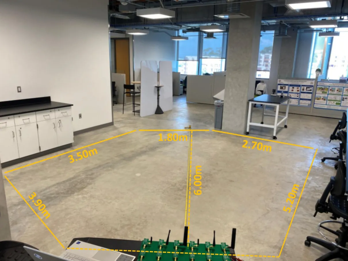
Moving target localization. To localize a single moving target with an acceptable level of ambiguity, NeuroRadar employs a six-sensor array with a λ/4 spacing and diverse carrier frequencies, as simulated in Section 4.3. Since NeuroRadar can only detect moving targets, we ask a volunteer to walk randomly within the radar’s field of view. The maximum distance of the target is around 6m, and the angle of view is about 90°, as shown in Figure 17. We employ a depth camera (StereoLabs ZED-2i) to obtain the ground-truth location and speed. We collect six segments of 10-minute (3,600s total) continuous data for training and testing. For each segment, we allocate the first 480s (80%) of data as training samples, reserving the last 120s (20%) as test samples. We then further segment the continuous data into 2s short frames with a 75% overlap, and each of the short frames becomes a training/test sample. This results in a total of 5,742 training samples and 1,422 test samples.
Here, we set ndly = 4 (Section 5.2), resulting in an input dimension of 12 × 500. From each frame, we evenly selected four data points, yielding four sets of location and velocity data: (x1, y1, u1, v1), (x2, y2, u2, v2),….…, (x4, y4, u4, v4). These sets were used as labels for the regression problem, thus making the output dimension of the neural network 1×16. The specific structure of the SNN model is outlined in Table 3.
| Type | Dimension | Channels | Kernel | Stride | Pool | |
|---|---|---|---|---|---|---|
| 1 | Conv. | 12 500 | 1 | 2 32 | 2 1 | 1 4 |
| 2 | Conv. | 6 118 | 64 | 3 24 | 1 1 | 1 2 |
| 3 | Conv. | 4 49 | 64 | 4 16 | 1 1 | 1 2 |
| 4 | Dense | 1 17 | 96 | N/A | N/A | N/A |
| 5 | Dense | 1 300 | N/A | N/A | N/A | N/A |
| 6 | Dense | 1 16 | N/A | N/A | N/A | N/A |
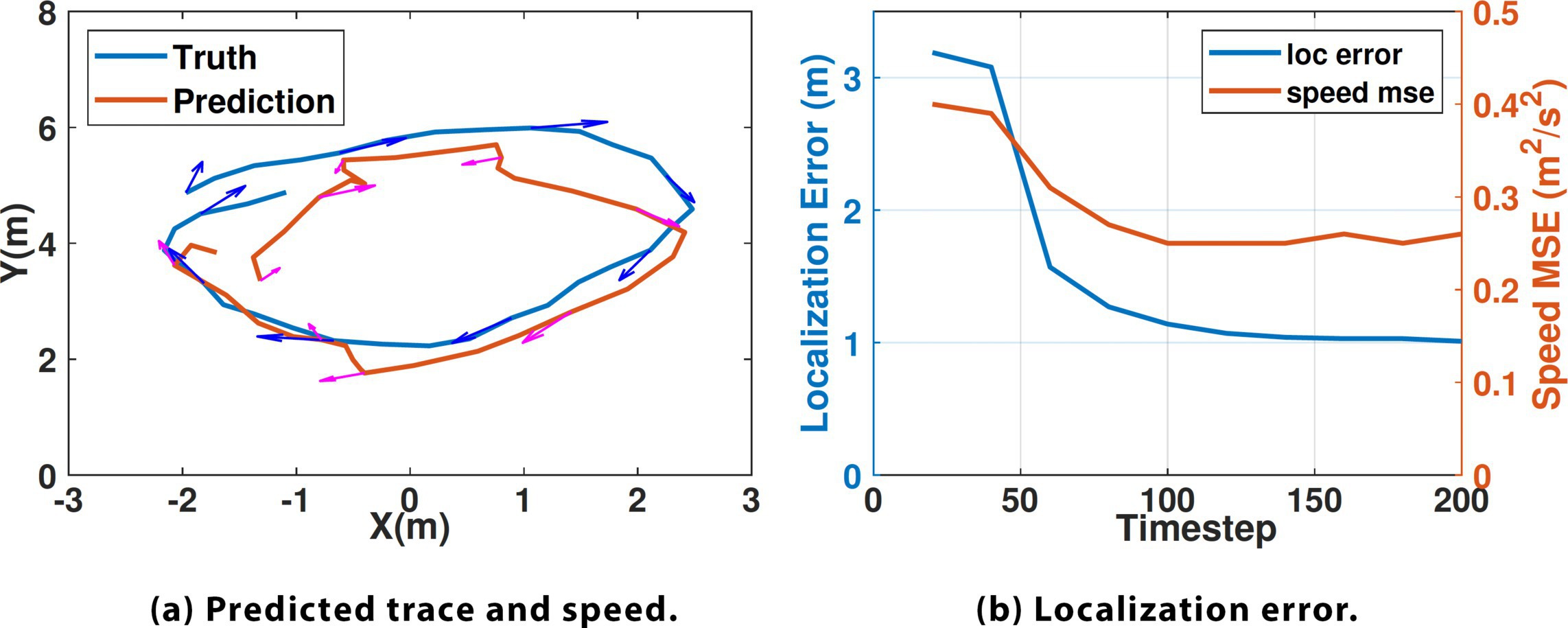
Figure 18a shows the localization result by combining the output of consecutive frames. Similar to the gesture recognition use case, the SNN needs to run for enough timesteps to yield a reasonable result. Figure 18b shows that with about 150 timesteps, a localization accuracy of 1m can be achieved. The mean squared error for speed estimation stabilizes at 0.25m2/s2. The result implies a tracking delay of 150ms, sufficient for our low-velocity indoor applications. Since we are filtering spike sequences to achieve a continuous value, errors are inevitable, and the accuracy is impacted.
To showcase the advantages of NeuroRadar, we compare it with a multi-tone (2.4GHz and 5.8GHz) Doppler radar system, Doorpler,10 which uses a conventional RF front-end architecture (Section 4.1) and signal-processing method. Due to the extra demodulation gain of SIL radar (Section 4.2), NeuroRadar provides a more extensive coverage area than Doorpler, even with 10dB lower Tx power. Due to its simple SIL structure and power-efficient design, NeuroRadar achieves one to two orders of magnitude of reduction in front-end power. The combination of FDA design and neural network allows NeuroRadar to obtain more abundant and accurate sensing information. Unlike Doorpler, which merely detects crossing events and their direction, NeuroRadar offers both location and speed estimation. At the same time, SNN processing significantly reduces the computational power, and the end-to-end system power consumption is reduced by 97%.
Related Work
Neuromorphic sensors. To achieve energy-efficient, real-time sensory data processing, neuromorphic sensors have been explored to perceive various types of signals, such as vision, tactile, auditory, chemicals, PH, and so on.24 They have shown great potential for personal healthcare monitoring,6 neuroprosthetics,15 and soft robotics.12 Built on this line of research, NeuroRadar represents a pioneering step in extending neuromorphic sensing into the RF domain.
SNN-based radar signal processing. Recent research has attempted to use SNNs to process radar signals to reduce power consumption and latency. With the radar front end unmodified, these works1,3,17,18,21 still rely on ADC sampling and signal pre-processing using traditional computing units (that is, CPU/DSP), achieving limited energy efficiency. In contrast, NeuroRadar adopts a novel front end that produces spike sequences and can directly interface with energy-efficient neuromorphic computing hardware.
Conclusion
In this work, we have introduced NeuroRadar, a novel and pioneering approach in radar systems that fully embraces the principles of neuromorphic sensing. Through the joint design of analog hardware and spike-signal processing, NeuroRadar achieves superior energy efficiency. Through gesture recognition and localization tasks, NeuroRadar has demonstrated its capability while maintaining a power consumption significantly lower than that of traditional radar systems. This research marks a significant step forward, providing a unique and innovative solution for radar sensing in energy-constrained IoT devices.
Acknowledgments
The work reported in this paper is supported in part by the NSF under Grants CNS-2312715, CNS-1901048, CNS-1925767, and CNS-2128588.







Join the Discussion (0)
Become a Member or Sign In to Post a Comment