Wearable computing platforms, such as smartwatches and head-mounted mixed reality displays, demand new input devices for high-fidelity interaction. We present AuraRing, a wearable magnetic tracking system designed for tracking fine-grained finger movement. The hardware consists of a ring with an embedded electromagnetic transmitter coil and a wristband with multiple sensor coils. By measuring the magnetic fields at different points around the wrist, AuraRing estimates the five degree-of-freedom pose of the ring. AuraRing is trained only on simulated data and requires no runtime supervised training, ensuring user and session independence. It has a dynamic accuracy of 4.4 mm, as measured through a user evaluation with optical ground truth. The ring is completely self-contained and consumes just 2.3 mW of power.
1. Introduction
New computing platforms are becoming increasingly coupled to the user. Wearable devices such as smartwatches, smart rings, and head-mounted mixed reality devices are offering unprecedented access to computing and information on the go. As computing platforms evolve from devices we carry with us to devices we wear on us, there is a renewed demand for input techniques that are decoupled from the display. These input devices must be continuously available and subtle to support various contexts of use while enabling robust and expressive interaction.
Many of today’s most effective input devices rely on continuous tracking of the fingers or handheld objects; smartphones and smartwatches track 2D finger position, a mouse tracks 2D hand position, and augmented reality devices like the Microsoft HoloLens 2 track the 3D pose of the finger. These proven input techniques stand in contrast to existing lines of research around sensor-based efforts to track finger motion, which often focus on discrete, gesture-based interactions.5,17,20 Although gesture recognition is useful, it is just one part of the interaction language needed for mobile wearable computing. For common tasks such as object manipulation, drawing, sliding, swipe-based text input, or body-pose reconstruction, an input device that supports absolute, continuous tracking with millimeter-level precision will be most appropriate. Moreover, building a gesture recognizer on top of a tracking system, instead of direct classification from a sensor stream, can enable input devices that are more robust and extensible (for example, supporting different users and contexts out of the box).
In this work, we present AuraRing,14 a precise, millimeter-level ring tracking system. AuraRing consists of two components: a wireless, self-contained ring and a wristband that tracks the absolute position and orientation of the ring with respect to the wristband in real time. The low-power, battery-operated ring generates an oscillating magnetic field around the hand. As the user moves their finger and wrist, the relative position and orientation of this field changes with respect to the wristband. Sensors embedded in the wristband measure these fields at different locations and use these measurements to estimate the pose of the ring with respect to the wristband. AuraRing is effectively a 5 degree-of-freedom (DoF) tracking system—that is, it tracks three positional components (x, y, z) and two rotational components (yaw and pitch) of pose. When the ring is worn, this allows AuraRing to capture flexion/extension and abduction/adduction of both the wrist and finger metacarpal joint.
Compared with prior work, our approach leverages common device form factors—a wristband and a ring—and does not require affixing magnets,3 iron-core coils,4 or magnetometers3 to the fingertips. AuraRing leverages the insight that an electromagnetic coil is better placed around the finger than on it. Our approach also delivers significant improvements in power, range, portability, and tracking precision. Compared to a typical commercial EM tracking system,15 AuraRing uses approximately 2000× less power in a much smaller form factor.
We present two tracking solutions that leverage this model—a optimization-based approach and a neural network approach trained only on simulated data. We demonstrate that at runtime, AuraRing can track finger motion across different users despite small changes in how the device is positioned on the wrist and finger.
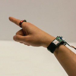
AuraRing offers a flexible solution for tracking the finger in either direct or indirect pointing tasks. We envision that AuraRing can be used either as a standalone input device or in tandem with a wrist-tracking solution. For standalone scenarios, AuraRing offers a rich input source for smartwatches or smart glasses. With AuraRing, a user can provide input using their finger and wrist while keeping their arm motionless at their side or resting on a table. This capability is particularly useful in public settings, when large-hand motions would be distracting and socially unacceptable.
AuraRing can also be used to track the absolute position of the finger in head space with respect to the user’s vision. In mixed reality scenarios, precise hand and finger tracking enables many compelling applications (Figure 1).

Figure 1. AuraRing is 5-DoF electromagnetic tracker that enables precise, accurate, and fine-grained finger tracking for AR, VR, and wearable applications. Left: A user writes the word “hello” in the air. Right: Using AuraRing to play a song in a music application on a smart glass.
Our primary contributions include the following:
- A hardware architecture for a one-axis transmitter ring and multi-sensor wristband that enables low-power finger tracking in a compact form-factor.
- Two tracking algorithms, including a physics-based iterative approach and a closed-form neural network approach to 5-DoF pose estimation.
- A system characterization and user evaluation demonstrating a dynamic tracking accuracy of 4.4 mm on a session-independent task (Figure 1).
2. Related Work
Magnetic tracking systems can be characterized by whether they use direct current (DC) or alternating current (AC) to produce magnetic fields. In DC tracking systems, a magnetic sensor, often a magnetometer, measures the magnetic field generated by an electromagnet or permanent magnet. This technique has seen extensive use in the HCI community, since magnetometers are commonly found in wearable devices and permanent magnets can be easily attached to the body. McIntosh et al.12 used permanent magnets affixed to the fingertip to interact with a smartwatch that measures the magnetic field direction and strength using magnetometers. Similarly, uTrack3 affixed a permanent magnet to the thumb and two magnetometers to the fingers to track 3D thumb pose. FingerPad2 also affixes a magnet to thumb but uses a Hall-effect sensor grid on the index fingernail to sense pinch gestures. Magnetic tracking systems that rely on permanent magnets have size and complexity advantages because they can rely on off-the-shelf magnets and magnetometers. However, this comes at the cost of precision. Magnetometers are generally limited in their accuracy and sampling rate, and such systems must contend with interference from the Earth’s geomagnetic field. As a result, the operating range of such systems is generally limited to several centimeters.
In contrast, AC magnetic tracking relies on one or more oscillating magnetic fields. AC electromagnetic tracking has a rich history of enabling precise, 6-DoF tracking.16,10 A typical electromagnetic tracking system contains a transmitter base station with a three-axis orthogonal coil transmitter and one or more three-axis receivers, typically realized using orthogonal coils. The oscillating magnetic flux through the coils induces an oscillating voltage of the same frequency, which can be amplified and measured. Filtering or synchronous detection is used to isolate the field of interest from other ambient magnetic fields, including the geomagnetic field. Original systems relied on iterative approaches to estimate the pose of the tracked objects. However, recent techniques have explored closed-form or closed-loop solutions that improve performance.9
AuraRing relies on short-range AC electromagnetic tracking to achieve precise tracking of a ring from a wristband. Unlike permanent magnet-based approaches, AuraRing is not susceptible to interference from the Earth’s geomagnetic field and the use of AC current significantly improves the tracking precision. Because AuraRing operates at distances on the order of 10 cm and relies on resonant coils pairs, it consumes significantly less power than commercial AC electromagnetic tracking devices, which often use several watts of power. The short range also significantly reduces the impact of interference from nearby metallic objects.
 2.2. Other approaches for finger tracking
Beyond magnetic tracking approaches, researchers have leveraged other sensing techniques to estimate fine-grained finger motion. Kim et al. used infrared illumination from the wrist to track hand pose.8 Although this method can enable full hand tracking, the form factor limits practicality. Project Soli20 uses radio frequency signals to recognize subtle finger gestures.
Camera-based approaches are a common approach to hand and finger tracking. These commonly rely on infrared depth sensing18 or markers on the hand.19 Unique placements of the cameras have led to interactive systems that offer subtle input.11,8 LightRing7 is most similar to AuraRing in its goals and uses a gyroscope and IR proximity sensor and optical mouse sensor respectively to track finger motion on a 2D surface. AuraRing differs in that it tracks the absolute 5-DoF pose of the finger and can be used for more than just 2D input on a surface.
3. Theory of Operation
Magnetic tracking is generally realized either with magnetometers to track a permanent magnet3,6 or with inductive coils to track an alternating current (AC) electromagnet.10,13,15,16,21,22 Static magnetic fields created by a permanent magnet are inseparable from the Earth’s geomagnetic field—an effect that becomes critical when operating at distances beyond a few centimeters. To isolate the signal of interest, AuraRing uses AC electromagnetic coils to generate a magnetic field at a particular frequency (32 kHz). Maxwell’s equations state that an AC magnetic field is generated when an AC electric current is passed through a wire coil. As depicted in Figure 2, AuraRing uses a wire coil wrapped around the ring to produce an oscillating magnetic field around the hand. According to Faraday’s law, a voltage is induced in the other sensor coils in the presence of this oscillating magnetic field. The induced voltage is proportional to rate of change of magnetic flux through the sensor coil, which will change as a function of the position and orientation of the sensor coils with respect to the transmitter coil.

Figure 2. AuraRing uses a wire coil wrapped on a ring to produce an AC magnetic field around the hand which is measured by three 3-axis coils embedded in a wristband.
Traditional 6-DoF electromagnetic trackers use a 3-axis transmitter and a 3-axis sensor coil, which is difficult to achieve in a ring form factor where size and battery life are paramount. However, a ring is a convenient form factor for a single-axis air core coil that wraps around the finger. Using a single-axis coil makes the entire system insensitive to changes in the roll of the transmitter along the magnetic axis; conveniently, such movement is not physically possible in finger-tracking scenarios. To compensate for the lack of three transmitter axes, AuraRing leverages three three-axis sensor coils embedded at known locations within a wristband. By measuring the magnetic fields at different points in space, AuraRing reconstructs the 3-DoF position and 2-DoF orientation of the ring. Figure 2 illustrates the configuration of the AuraRing transmitter and sensors as well as the coordinate systems used throughout this paper.
We construct a physics-based simulation to model the behavior of our system under different configurations, such as changing the number or placement of sensor coils. Because the ring diameter is much smaller compared to the distance between the ring and wristband, we use standard magnetic field equations to model the ring as a dipole emitter. This magnetic field model represents the inverse of the tracking problem—it estimates the magnetic fields given the ring position, whereas the tracking problem seeks to estimate the ring position given measurements of the magnetic field. This is useful for simulation and it also forms the basis of the optimization-based tracking algorithm discussed in Section 6.1. In this paper, we adopt the notation Av to represent the v vector in the A coordinate frame. The notation
 represents a rotation transformation from the A to B coordinate frame. In practice, these transforms are implemented using quaternion algebra, but other representations would be appropriate as well.
The model seeks to estimate the magnetic field vector measured at each sensor coil, si, where si indicates the sensor coil of interest. Because the transmitter is embedded within the object to be tracked, we first conduct a series of coordinate system transformations to reduce the model to simple dipole analysis with known closed form solutions. Let d be the dipole coordinate frame with the magnetic axis oriented in the z-direction, that is, in a direction along the finger (see Figure 2). This is coincident with the ring coordinate frame. Let w be the wristband coordinate frame, which contains multiple sensors, si, at positions
 and orientations
 , as depicted in Figure 2. These transforms are defined in the wristband coordinate frame and are known from the 3D geometry of the wristband enclosure and electronics.
Given any possible position of the dipole/ring with respect to the wristband (wd), and the geometry of the sensors
 , we first compute the position of the sensor in the dipole frame:

We can decompose this sensor position vector,
 , into x, y, and z components (see Figure 2) and compute the distance between the dipole and sensor,
 . We then use standard the magnetic dipole equation derived from the Biot-Savart law under quasistatic assumptions to compute the expected magnetic field at each sensor location
 . This equation captures the magnetic field at any point around a standard dipole. Note that we omit the magnetic dipole constants here for brevity and because we are only interested in the relative field strengths.

This gives us the magnetic field vectors at each sensor in the ring/dipole coordinate frame. To estimate what each sensor would measure, we rotate once more to compute this magnetic field in the sensor frame of reference:

4. AuraRing Hardware
The AuraRing system consists of a ring that generates an AC magnetic field and a wristband with three embedded sensors that measure the resulting fields. Figure 3 depicts the AuraRing system components.

Figure 3. AuraRing contains two controller and three sensor boards embedded in a wristband and a ring worn device.
In designing AuraRing, we pursued a design that would resemble device form factors that users are already accustomed to in order to present a plausible path forward for everyday use. For the ring-based transmitter, rather than affixing an iron-core coil4 or permanent magnet2,3 to the top of the finger, we designed a custom electromagnet transmitter compatible with a ring form factor. In doing so, we were forced to put minimal digital electronics on the ring to ensure a slim form factor and minimize power consumption. AuraRing’s ring consists of a single-axis low-profile transmitter coil that emits a magnetic field oscillating at 32.768 kHz. The transmitter coil consists of 600 turns of 42 AWG magnet wire wound around a 3D-printed ABS ring with a diameter of 20 mm. The inductance of the coil is approximately 15 mH.
The AuraRing wristband consists of three sensors and two controller boards as depicted in Figure 3 (right). At a high level, the sensor boards each measure a magnetic field, while the controller boards convert these measurements to digital signals and communicate them to a host computer.
The sensing pipeline is adapted from the signal processing techniques validated for use in electromagnetic tracking applications in Aura.21 The sensor boardazs transduce the magnetic field generated by the ring using an off-the-shelf three-axis orthogonal receiver coil (Grupo Premo 3DC15). The signal from each axis is fed to an amplifier (INA826) with a gain of 44 dB. We then use a low-noise and low-voltage drop Schottky diode network (SMS7630) in a full-wave bridge rectifier configuration to demodulate each of the channels. This passive configuration effectively demodulates the field with minimal power consumption and complexity.
These magnitude signals are passed to controller boards where an SAR analog-to-digital converter (AD7265) samples the data. Finally, the sampled data is passed to an ultra-low power MCU where the data is collected and sent to a host computer over USB at 472 kHz.
5. Calibration
AuraRing’s tracking algorithms have, at their core, a physics model, described in Section 3.2. This can be directly used in a parametric model-based tracking algorithm (see Section 6.1) or can be used to generate synthetic data for model training (see Section 6.2). However, before the physics model can accurately describe the AuraRing measurements, we must learn a number of parameters, such as channel gains and precise sensor positions. In a precise manufacturing environment, these parameters can likely be set based on an analysis of the system geometry and electronics. However, in our prototype, due to the tolerances of 3D printed parts and our selection of electronic components, we opt to learn these parameters empirically by collecting and using data from an optical motion capture system. This calibration is a one-time process based on data collected in a controlled environment. After this procedure, AuraRing can be used without any additional training. In the following sections, we describe our data collection setup, the calibration model, and learning procedure. Figure 4 shows a high-level overview of the calibration process and how it relates to the runtime pose estimation task.

Figure 4. The AuraRing system needs a one-time factory calibration to match the synthetic data to its measurements. In real time, the iterative model uses this calibration to refine the pose estimation and the neural network model regresses directly to pose.
We use a 10-cameraa optical motion capture system (calibrated accuracy of 0.1mm) to track the ground truth position and orientation of the wrist and ring. To facilitate this, we place IR retroreflective markers on both devices, as shown in Figure 5. These markers are placed on temporary 3D-printed adapters to ensure they remain at known locations. Let m be the coordinate system corresponding to the motion capture system, r be the ring’s coordinate system, and w be the wristband coordinate system, as defined in Section 3.2. Here, we distinguish between the ring frame (r, used here) and the dipole frame (d, used in the magnetic field calculations). While these two frames are ideally coincident, the magnetic center of the ring may be slightly offset because it is hand-wound around the ring. The motion capture system reports the pose of the wristband
 and ring
 in the motion capture coordinate frame at 240 Hz. Software in Python on a PC logs both the motion capture data and AuraRing sensor data to disk for offline analysis.

Figure 5. We place retroreflective markers on the ring and wristband to get the ground truth measurement.
We first preprocess all of the motion capture data to align the rigid body coordinate frames to the w and r frames defined by the device geometry, as shown in Figure 2. Next, we reconstruct the relative pose of the ring in wrist space by applying another coordinate system transformation.


Finally, we synchronize the sensor stream from AuraRing (472 Hz) with the ground truth ring pose stream from motion capture system (240 Hz). Such synchronization requires the comparison of correlated events in each data stream, but the raw sensor data is uncorrelated with the ground truth pose data. To address this challenge, we use the time alignment technique presented in Aura.21 We align the two streams by using the ground truth ring pose as an input to the uncalibrated magnetic field model (Section 3.2) to approximate the magnetic fields at each sensor and comparing these fields to the observed sensor values. Because this model is as yet uncalibrated, this simulated sensor stream does not perfectly match the observed data, but is correlated enough for alignment purposes. We use these signals to achieve alignment at the start and end of the recorded data streams. We then resample the AuraRing signal through interpolation to 240 Hz to achieve frame-by-frame alignment with the ground truth signal.
The signal processing pipeline in AuraRing transduces the incident magnetic field to a digital value. For a given ring pose, we need to be able to estimate the digital values reported by each sensor. Doing so accurately requires additional calibration parameters that define the sensor model, which describes how a given pose manifests as sensor measurements. These parameters model effects like the sensitivity of each coil and the relative positioning of the sensor coil on the PCB. Altogether, they capture offsets between the motion capture positions and the effective magnetic origins as well as the effects of the AuraRing analog signal processing pipeline. These parameters are expected to remain constant throughout the lifetime of the device. Below, we briefly outline these parameters and how they fit into the AuraRing sensor model.
5.2.1. Coordinate system offsets. Due to manufacturing tolerances, the exact position of each sensor with respect to the wristband coordinate system,
, does not exactly align with the computed values from the CAD design
 . Since the sensor model estimates the magnetic fields at the sensor positions, it is essential that the sensor pose be as accurate as possible. Consequently, we define offset positions
 and orientations (Ri,offset to refine each sensor pose in the wristband frame. These slack terms are expected to be small—on the order of a couple of millimeters or degrees—but they make a significant difference in the tracking performance. The following equations describe how the slack terms are used with the CAD measurements to obtain the exact sensor pose.


We use a similar technique to define the dipole coordinate frame with respect to the ring coordinate frame, wherec rd and
 represent the offset between the r and d frames. Again, this is done to account for the practical side effects of winding our own coils.


Specifically, the unknown parameters are
 (3 terms), Ri,offset (4 terms in quaternion form), rd (3 terms), and
 (4 terms in quaternion form).
5.2.2. Modeling analog signal chain. We then use the model in Section 3.2 to compute
 , the magnetic field in each sensor reference frame. However, the sensors and amplitude demodulation pipeline do not represent a perfect measurement of the magnetic field. For one, the rectifier-based demodulation scheme only provides an unsigned estimate of the field strength along each axis. Moreover, each channel has a slightly different gain, due to different sensitivities and manufacturing tolerances of both the sensor coil and amplifiers. We also model the effects of noise and the diode forward voltage drop. Specifically, we estimate the sensor measurement (xi,j) as a function of the field
 and the channel gain (gi,j), noise (ni,j), and bias (bi,j), where i = {1, 2, 3} indicates the sensor and j = {x, y, z} indicates the axis of a particular sensor.

For a given sensor coil, i, there are 9 signal chain parameters to learn: gi,j, ni,j, and bi,j for j = {x, y, z}.
5.3. Learning sensor model parameters
We learn the set of 23 parameters (14 from coordinate system offsets and 9 from the analog signal chain) separately for each sensor, i. To learn these parameters, we collected a dataset that captures a wide range of motion of the ring. One of the authors wore the wristband while using the other hand to move and rotate the ring transmitter freely within in a volume around the hand. During this process, the ring and wrist pose are captured by the motion capture system and aligned as previously described. The data was explicitly collected without wearing the ring so that this dataset contains 6-DoF motion of the ring. Otherwise, the data would be constrained by the 4-DoF wrist and finger kinematics of a particular user and it may be possible to overfit these parameters to that user.
We took a random sample of 30k frames from this data-set to use for learning and formulated the problem as a nonlinear optimization problem, which we solve using Ceres Solver.1 We learn the 23 parameters for each sensor coil independently. In doing so, the solver seeks to find the parameter set that minimizes the difference between the observed sensor values and the estimated sensor values, computed according to the observed pose and the sensor model. The solver uses the Levenberg-Marquardt trust region algorithm for minimization.
Upon convergence, this results in a set of parameters that can be used to estimate the sensor measurements as a function of pose. Figure 6 shows the correlation between the sensor estimates and actual measurements on this dataset before and after applying the sensor model presented here. Before applying the sensor model, the estimates have a 0.564 Spearman’s rank-order correlation with the actual measurements. After applying the sensor model, the correlation increases to 0.995, validating the effectiveness of this model.

Figure 6. The one-time factory calibration process is necessary to match the synthetic data to the data measured by AuraRing.
6. Tracking Algorithm
Taken together, the magnetic field model and sensor model represent a forward model of the system—they estimate the sensor values given the ring pose. To track the ring at runtime, we must solve the reverse problem—estimating the ring pose given the sensor values. We implemented two different tracking algorithms to solve this reverse problem and estimate the 5-DoF pose of the ring. The first is an iterative optimization-based solution and the second is a neural network that approximates a closed form solution to the reverse problem.
6.1. Approach 1: iterative model
The iterative model is similar to the method of learning calibration parameters discussed in Section 5.3, but operates on each frame separately. However, instead of estimating the calibration parameters, these remain fixed and the solver estimates the pose of the ring. We use a nonlinear optimizer1 with the Levenberg-Marquardt algorithm to iteratively find the most likely pose. When a new packet of sensor data arrives, the solver minimizes the error between the observed sensor values and the sensor values predicted by the forward model (xi,j, Equation 10). It is allowed to run for a maximum of 100 iterations. For the first frame, the initial pose state is set to a default pose with the index finger pointing forward without bending. For subsequent frames, the solver uses the solution to the previous frame as the initial state. Further improvements in speed and accuracy may be possible by using a Kalman filter to proactively estimate the next ring pose.
6.2. Approach 2: neural network-based tracking
As an alternative to the iterative model, we also developed closed form approximations to the reverse problem that are optimized for use on low-power devices. Specifically, we trained a simple neural network to predict both the 3 DoF position and 2 DoF orientation of the ring directly from the magnetic measurements. Notably, we use only synthetically generated data to train the network, eliminating any user or session dependence.
6.2.1. Generating training data. Neural networks are particularly sensitive to the quality of the training data. In this tracking problem, insufficient sampling of any portion of the tracking space will result in poor performance. An appropriate neural network approximation to this problem either requires a prohibitively large amount of training data or a smaller but uniformly distributed set of data. To eliminate any dependence on runtime training data and to achieve precise control over the sampling distribution of the training data, we train the network entirely from synthetic data generated by our simulated magnetic and sensor models, after the one-time calibration. This eliminates issues of over-fitting to a particular user’s hand or to a particular training session. We randomly generated different ring poses within a volume relative to the wrist that spans possible positions of the ring for most adults. Specifically, assuming the coordinate system defined in Figure 2, the generated data covers a volume defined by – 70 mm < X < 90 mm, –125 mm < Y < 60 mm, and −150 mm < Z < −60 mm. We also add a random 3-DoF rotation to each point to complete the dataset of random poses.
We then use the sensor model to estimate the values of AuraRing’s sensors at each pose. Since AuraRing uses 3 three-axis receivers and each axis could be in or out of phase with the transmitter, there are 29 = 512 possible combination of phase states for a given frame. However, due to the spatial geometry of our sensors and the kinematic structure of a hand, the majority of these states are not feasible during normal use. For example, because the ring always lies in front of (negative z-direction) the wristband, all of the z-channels of the sensors will have the same phase. In fact, after reviewing the generated data we found that only 10 of these 512 combinations are feasible. We drop any data from the generated dataset that does not match 1 of these 10 feasible phase states. Since training uses only simulated data, one could easily change these constraints or even add another state and train a larger network to support different kinds of tracking tasks. After this culling process, the dataset consists of 166,465 points.
6.2.2. Neural network training. We use two computationally simple two-layer feed-forward network to regress to a position vector and the 2-DoF orientation of the ring. Both networks have a single hidden layer of 128 nodes to fit a function that maps the 9 observed sensor values to a 3-dimensional position vector and to a 3-dimensional direction vector. We use a direction vector to specify orientation in order to remain invariant to the roll of the ring. Training using the synthetic dataset is performed in MATLAB with the Levenberg-Marquardt algorithm. With CPU training on a single core of a Xeon E3-1240 processor, training takes about 6 hours. Mean training error was 3.06 mm for the position model and 5.45° for the orientation model. Orientation error was calculated by computing the angle between the two direction vectors.
7. System Evaluation
7.1. User evaluation procedure
We evaluate the tracking accuracy of each of these models using data collected from users who we invited to try AuraRing. We do this to provide a realistic estimate of real-world performance under challenging conditions such as different hand size, shape, flexibility, slippage of the devices on the hand and finger, and changes in environmental factors. We recruited 14 participants (5 M, 9 F) with different hand sizes to wear AuraRing while exercising the full range of motion of their wrist and fingers. The data collection was carried out in the same 10-camera motion capture lab used to calibrate the sensor model. The researchers helped the participants put on the wristband and placed the ring on the index finger of the right hand. The average distance between the ring and wristband across all participants was 12.3 cm (min: 10.8 cm, max: 14.3 cm). During operation, the closest distance between the ring and wristband was 8.1 cm and the furthest distance was 15.6 cm.
As before, markers were placed on an attachment to the ring and wristband to facilitate optical tracking. The participants were asked to freely and naturally move their wrist and finger for 10 min, while being sure to exercise all possible joint motion. During this time, the ground-truth pose and the magnetic sensor data were recorded by a Python program. Altogether, this resulted in more than 2 h of data consisting of over 1.7 million synchronized data points.
We compare the tracking accuracy for both the iterative and neural network model. The table here shows the mean accuracy for the pose of the finger using each algorithm. The full error distribution is shown in the cumulative distribution function (CDF) in Figure 7 that aggregates data across all 12 participants. These results show a mean tracking error of 4.41 mm for the iterative model and 6.07 mm for the neural network model. For orientation, the iterative model tracks the forward direction of the finger with a mean error of 4.65° and the neural network tracks with a mean error of 8.35°.

Figure 7. CDF of 3D position tracking among all participants using the iterative model vs. the neural network model.

Table. The position and orientation error among 12 participants using iterative and neural network models.
8. AuraRing Capabilities
AuraRing provides a continuous, precise ring tracking system upon which a number of interactions, such as pointing, tapping, hand pose reconstruction and custom gestures, can be built. For example, by projecting forward from the ring, we can track the fingertip position and enable 2D drawing or handwriting recognition on a virtual surface placed in front of the hand. Figure 8 (left) shows an example of a user’s handwriting using AuraRing.

Figure 8. (Left) AuraRing enables drawing in 2D or 3D space. (Middle) Tracking data can be used to animate a virtual hand in space. (Right) AuraRing is capable of measuring high-speed events such as taps. (Right top): nine raw sensor measurements. (Right bottom): Spectrogram of the recorded data.
Because AuraRing provides information about the wrist and index finger, it can be used to reconstruct hand pose in mixed reality scenarios. We implemented an inverse-kinematics solution that estimates wrist and finger joint angles from the estimated ring pose and renders this hand to the user (Figure 8, center).
The speed and precision which AuraRing’s magnetic tracking enables unlock additional functionality not commonly found in wearable sensing systems. With a data rate of 472 Hz and a sensor bandwidth much higher than this, AuraRing is capable of measuring high-speed events, such as taps on physical surfaces. To illustrate this, Figure 8 (right) shows a series of taps of varying intensities on a tabletop surface after a period of freely moving the finger and wrist in space. While hand and finger motion contain mostly low-frequency content, taps are immediately distinguishable due to their broadband spectrum.
9. Conclusion
In this work, we present AuraRing, a wearable ring and wristband that enables precise, subtle, and accurate finger tracking. Using minimal, low-power electronics on the ring, AuraRing can operate for about a day on self-contained batteries. We presented two methods for tracking, a neural network-based approach and an iterative model. AuraRing only needs a one-time factory calibration process to match its synthetic data to sensor measurements and can track with a mean error of 4.4 mm.
 This work is licensed under a Creative Commons Attribution International 4.0 License.


Join the Discussion (0)
Become a Member or Sign In to Post a Comment