3D printing hardware is rapidly scaling up to output continuous mixtures of multiple materials at increasing resolution over ever larger print volumes. This poses an enormous computational challenge: large high-resolution prints comprise trillions of voxels and petabytes of data, and modeling and describing the input with spatially varying material mixtures at this scale are simply challenging. Existing 3D printing software is insufficient; in particular, most software is designed to support only a few million primitives, with discrete material choices per object. We present OpenFab, a programmable pipeline for synthesis of multimaterial 3D printed objects that is inspired by RenderMan and modern GPU pipelines. The pipeline supports procedural evaluation of geometric detail and material composition, using shader-like fablets, allowing models to be specified easily and efficiently. The pipeline is implemented in a streaming fashion: only a small fraction of the final volume is stored in memory, and output is fed to the printer with a little startup delay. We demonstrate it on a variety of multimaterial objects.
1. Introduction
State-of-the-art 3D printing hardware is capable of mixing many materials at up to 100s of dots per inch resolution, using technologies such as photopolymer phase-change inkjet technology. Each layer of the model is ultimately fed to the printer as a full-resolution bitmap where each “pixel” specifies a single material and all layers together define on the order of 108 voxels per cubic inch. This poses an enormous computational challenge as the resulting data is far too large to directly precompute and store; a single cubic foot at this resolution requires at least 1011 voxels and terabytes of storage. Even for small objects, the computation, memory, and storage demands are large.
At the same time, it is challenging for users to specify continuous multimaterial mixtures at high resolution. Current printer software is designed to process polygon meshes with a single material per object. This makes it impossible to provide a continuous gradation between multiple materials, an important capability of the underlying printer hardware that is essential to many advanced multimaterial applications (e.g., Wang et al.20). Similarly, there is no support for decoupling material from geometry definition and thus no ability to specify material templates that can be reused (e.g., repeating a pattern that defines a composite material, or defining a procedural gradation for functionally graded materials).
We think the right way to drive multimaterial 3D printers is a programmable synthesis pipeline, akin to the rendering pipeline. Instead of a static mesh per piece of material, OpenFab describes a procedural method to synthesize the final voxels of material at full printer resolution on demand. This provides efficient storage and communication, as well as resolution independence for different hardware and output contexts. It also decouples material definition from geometry. A domain-specific language and pipeline features specific to 3D printing make it much easier for users to specify many types of procedurally printed output than they could by writing standalone programs for every different material or fabrication application.
The OpenFab pipeline offers an expressive programming model for procedurally specifying the geometry and material of printable objects. A scene graph describes geometry and attributes, although fablets procedurally modify the geometry and define the material composition much like shaders in the rendering pipeline. Fablets are written in a domain-specific language (OpenFL) and provide a flexible toolset that supports many common material specification tasks.
We also propose a scalable architecture for implementing the OpenFab pipeline. As the total computational cost is large and it is impossible to fit the entire output volume into memory, the pipeline is designed to progressively stream output to the printer with a minimal up-front precomputation and with only a small slab of the volume kept in memory at any one time. An OpenFL compiler analyzes and transforms the procedural computation described by the fablets as needed for efficient implementation in the fabrication pipeline.
We evaluate the system on a variety of multimaterial 3D objects that have been specified and computed using our pipeline. We discuss how our system can be used to easily describe metamaterials, graded materials, and objects that contain materials with varied appearance and deformation properties. We print a number of results using a commercial multimaterial 3D printer and evaluate the performance of our prototype implementation.
2. Background and Related Work
“3D printing” is an umbrella term for a variety of additive manufacturing processes where parts are built up from constituent materials, typically one layer at a time, in an incremental fashion. Processes vary by what kind of materials they work with (polymers, ceramics, metals, etc.) and how the material itself is deposited and bonded together. Some processes such as Polyjet, stereolithography (SLA), selective laser sintering (SLS), and powder-binder printing have direct control over the geometry of the part at the individual voxel level. Other processes such as fused deposition modeling (FDM)—which has been popularized by entry-level desktop systems from MakerBot, Ultimaker, and others—perform material deposition through a continuous vector motion that does not allow for precise voxel-level control. Further, some 3D printing processes allow for the precise deposition of different materials at the voxel level, most notably the Connex systems from Objet and the 3D Systems Projet MJP 5600.
Our work specifically targets state-of-the art 3D printing processes that allow for precise deposition of different materials at each voxel. Such processes can print at resolutions higher than 300 dots per inch, where each printed layer can be represented as a bitmap, and each pixel in the bitmap specifies the particular material type that needs to be deposited at that location. All layers together define on the order of 108 voxels per cubic inch.
Traditionally, 3D printing has synthesized uniform material objects defined by unstructured surface meshes.1 Multiple materials are supported by statically assigning a single material to each mesh. Various companies have created proprietary formats to support their specific equipment. Nevertheless, with current printing software, it is unclear how the geometric data is translated to machine instructions, making the printing process difficult to control from outside. Open-source efforts (e.g., RepRap and Fab@Home) largely target FDM printing processes, which are motion vector-based, low-resolution, and low-throughput architectures, with limited support for multiple materials (multiple materials are handled as separate STL files). The Additive Manufacturing File Format (AMF) standard3 allows description of object geometry, its composition, and color. Colors and materials can be specified with limited proceduralism, using simple expressions from voxel coordinates to material choices, but these have limited expressive power, and no architecture has been proposed to efficiently implement this model.
In contrast to the model-oriented descriptions supported by traditional 3D printing software, standard APIs and formats in 3D rendering and 2D printing describe how an output device should synthesize an image.2,5,16,17 Rendering pipelines, in particular, balance flexibility and efficient implementation by combining a fixed pipeline with user-programmable stages, and programmable shaders decouple geometry from material description. Our fabrication pipeline is inspired by the success of programmable rendering pipelines and uses shader-like fablets to describe microgeometry and material composition. Our scene description parallels standard scene graph representations,4 with extensions specific to fabrication, and without many complexities necessary for animation and interactivity. More detailed treatment of related work is given in the original version of this paper.19
3. Design Philosophy
Mixing many materials with different optical and mechanical characteristics at inkjet printer resolution allows extremely complex objects with countless unique and spatially varying properties to be synthesized directly from a digital description. At the same time, print volumes and speed are growing, although cost is falling, putting additive multimaterial manufacturing within reach of much more applications. These trends led us to several major principles, which guided our design as follows:
- Continuous material definition. To unlock the full capabilities of printer hardware, our system should allow continuous material definition at full printer resolution.
- Streaming architecture. In order to achieve scalability necessary for printing large build volumes at native resolution, the OpenFab pipeline should only use local storage and computation wherever possible, streaming over the output volume in the order required by the printer. It should also require as little up-front precomputation as possible, to minimize printer startup delay.
- Procedural synthesis. Expressive tools, especially a shader-like language and programming model, provide a more natural way to describe complex optical and mechanical material logic than is currently possible with static meshes per material. Procedural synthesis also supports scalability, trading memory for computation: the material composition and geometric detail do not have to be stored explicitly but can be computed procedurally, as required by the printer.
- Decoupling material from geometry. Complex material logic should be defined independently of the mesh geometry and be reusable across models.
- Automatic adaptation to hardware. Procedural synthesis of surface and volume detail provides resolution independence for different output sizes and resolution. Automatically normalizing and dithering the multimaterial mixtures, accounting for physical constraints such as different materials expanding or contracting when cured, dramatically simplify the development of device-independent procedural materials.
4. Programming Model
To meet these design goals, we propose a programmable pipeline abstraction for 3D printing (Figure 1). Similar to rendering pipelines, some of the stages are fixed and others are programmable by the user. The role of the pipeline is to process a combination of geometric input, image textures, and fablets to synthesize device-specific fabrication output. The user controls the process by defining geometry and textures, setting pipeline attributes and options, and writing fablets. User-programmable fablets procedurally transform and compute the attributes at each vertex of the object mesh and compute the material mixture output at each point within the mesh volume.

Figure 1. The OpenFab pipeline defines a programming model for synthesizing continuous volumetric material mixtures for 3D printing. As an input (blue), it takes a scene graph describing a set of object boundary representations, textures, printer materials, and user-programmable fablets—similar to shaders. From this input, it generates a discrete volumetric material definition that is device specific. Some stages are fixed function (gray), controlled by high-level parameters and printer characteristics, although fablet stages (red) are programmable by the user.
The input to the pipeline is a fab world, a scene graph-like description that consists of object boundary representations and associated attributes such as transforms, image texture inputs, and fablets. Recurring shapes can be defined and instanced multiple times. Objects are also given priorities, which allow CSG-like operations and control the treatment of overlapping regions. (If two or more objects cover the same voxel, that voxel is assigned to the object with a higher priority value.)
In the first stage of the pipeline, the surface of the input objects is discretized via tessellation to match the desired output resolution. Tessellation generates micropolygon primitives—the common surface representation throughout the pipeline—with user-defined attributes interpolated from the input object.
Next, the surface stage of the user’s fablet program is evaluated over these micropolygons. The surface fablet stage is conceptually similar to a vertex shader: it evaluates point-wise, given a vertex position and interpolated attributes as input, and performs arbitrary computation, such as sampling from textures, to produce a (potentially displaced) output position and some number of output attributes. Procedural displacement provides a mechanism for describing surface microgeometry in arbitrary detail that would be infeasible to explicitly model in the input objects.
The next stage discretizes the volume enclosed by objects via voxelization. It is critical to use consistent, crack-free rules for voxelization. We follow the rules of 26-separating voxelization.7 Consider a multipart assembly where parts are printed separately. To ensure the assembly fits together, each voxel overlapping the shared geometry along part boundaries must be consistently assigned to exactly one part.
After voxelization, the volume stage of the fablet is evaluated over each voxel. This stage receives interpolated attributes as input and performs arbitrary computation to produce a floating point-valued mixture of the available printing materials. In addition to standard arithmetic, control flow, and texture sampling functionality, the volume fablet stage also allows querying the distance to the nearest point on the surface, and any surface attributes at that point. When defining materials volumetrically, it is often useful to be able to determine the relative position of a given voxel with respect to the object boundary.12 Consider the scenario where we would like to print a textured object. Unlike rendering, we cannot assign colors simply to the infinitesimal outermost layer of the surface; rather, the printer needs to deposit a certain volume of layered material in order to achieve a particular color, reflectance, and scattering behavior.
Finally, the dither stage performs volumetric quantization and discretization of material quantities to match the capability of the target printer before handing the result to a specific printer driver. Our initial implementation included a streaming raster slice backend that is appropriate for a drop-on-demand 3D printers and a legacy backend that generates per-material STL meshes for use with traditional commercial printer software.
Fablets are written in OpenFL, a C-like programming language similar to shader languages such as HLSL.5 Unlike most shader languages, OpenFL describes both surface and volume functionality together as methods on a single fablet object. Uniform parameters, such as texture and material IDs, are also declared in the object. OpenFL includes standard functions for common math, texturing, and other routines. Unique to our domain, it also includes functions to query the distance to the nearest point on the surface, as well as any interpolated mesh attributes at that point.
To understand how fablets can be used to define procedural surface detail and continuous volumetric material variation, consider the example as shown in Figure 2. One side is flat and texture mapped with the foreground image, whereas the other side is displaced according to the desired brightness of the shadow background image. This object is defined by the following fablet:

Figure 2. The front face of the postcard (left) is texture mapped using a foreground image. The back (right) displaces the surface to create a spatially varying transmission according to a combined foreground and background image. The result is a hidden background image, which only appears when backlit (center).
Material and texture handles are declared as attributes of the fablet, along with parameters for the dimensions of the rectangular border, maximum thickness, and the depth into the volume to which the texture should be deposited on the front face.
The surface phase takes as arguments the position, normal, and texture coordinates defined over the mesh, as well as a per-vertex flag indicating the face of the cube (front, back, or side). If the currently processed vertex is on the back face, the fablet computes a material thickness based on the luminance of the background image and displaces the mesh accordingly. It creates a fixed-depth border in a narrow band around the edges defined by the border parameter. Outside the back face, it performs no displacement and simply returns the original vertex position.

The volume phase takes as its argument the 3D position of the center of the currently processed voxel. It then uses the face flag from the nearest surface point to determine if it is near the front face. If it is and the distance to the surface is within textureDepth, it samples the foreground image texture based on the nearest surface texture coordinates and mixes black and white materials based on the brightness at that point. Note that the texture cannot simply be deposited in an infinitesimal layer on the surface. To show up clearly in real materials, it is usually necessary to deposit colors down from the surface to some depth inside the interior volume. Elsewhere in the object, it outputs plain white material.
5. Architecture
The OpenFab pipeline is inspired by Reyes8 and modern realtime rendering APIs such as OpenGL and Direct3D, and it is similarly designed to facilitate efficient implementation. Specifically, it is designed to allow a streaming implementation, starting to produce output quickly after startup and driving the printer on demand within a fixed and controllable memory footprint. Additionally, the fablet programming model is designed to admit data parallel computation in the same style as shaders in rendering.
Our reference implementation was built to stream output with a fixed memory budget and low startup time. It is a scalable foundation for a high performance implementation, but many individual stages are internally unoptimized. Nonetheless, it is more than fast enough to keep up with currently available printers.
The architecture of our implementation is shown in Figure 3 and proceeds as follows:

Figure 3. The architecture of the OpenFab implementation is designed to stream over large, high-resolution print volumes with a fixed memory budget. The printing volume is divided into slabs along the primary printer axis, sized to bound memory usage. The pipeline processes one slab at a time and streams the output to the printer. Minimizing the amount of precomputation before streaming begins keeps startup time to a minimum, letting the printer start working almost immediately after OpenFab begins processing. Intermediate results such as tessellated geometry that span slab boundaries are cached for reuse, and the caches are also set to a fixed maximum size.
Precompute acceleration structures
for each slab, in printer order:
for each shape overlapping slab:
Compute surface microgeometry and attributes
Compute voxels and material composition
Normalize and dither materials to device capability
Output slab to printer
We begin by calculating bounds for each shape in the scene. Because fablets can displace surface geometry, this is not known directly from the input. Users provide maximum displacement bounds, but we additionally execute an interval arithmetic variant of the surface fablet stage to automatically infer displacement bounds as well6 and use the minimum of the user-provided and inferred bound.
We next create acceleration structures to speed up the nearest surface point queries performed in the volume fablet stage. We build a bounding volume hierarchy (BVH) that spatially partitions the base primitives of the input mesh, conservatively accounting for possible displacement using the displacement bounds calculated in the prior stage. This upfront process is fast because it is performed on the untessellated base primitives of the input.
If the target printer requires support structures, we pre-calculate the places where such support is needed. We use a fast, high-resolution, fixed-point rasterizer to perform an orthographic Z-buffer rendering along the print platform movement (z) axis. We conservatively dilate each primitive to account for any possible displacement using the bounds calculated in the first stage. The resulting depth map contains the highest point along the z axis at which the material is present for each voxel column represented by the given depth sample. During the later output phase, if a given voxel is void we output support if and only if the height of that voxel is lower than the highest populated voxel for that particular voxel column as recorded in the depth map (Figure 4).

Figure 4. A 2D representation of our support generation approach. Voxels in green and yellow are part of the object being printed. Voxels in gray are support voxels. Voxels in yellow are part of the depth map that is generated with a high-resolution, fixed-point rasterizer. Support voxels are generated for empty voxels if there is a voxel in the depth map above them.
 5.2. Slab processing (outer loop)
To begin printing, we subdivide the print volume into slabs. The size of the slab is dynamically calculated based on target memory usage and is a function of the resolution of the print and the total build volume. As we process each slab, we maintain a working set of shapes whose bounding volume intersects the current slab. As we begin the processing of each slab, we update the working set by removing shapes that are now beyond the current slab and adding ones that are now under the slab’s domain.
5.3. Shape processing (inner loop)
Within the working set, we sort objects by user-provided priority, processing from the highest to lowest priority and immediately discarding any newly generated voxels that are already occupied. Early culling makes fablet evaluation efficient: only one fablet (the one assigned to the highest priority object) gets evaluated per voxel.
The first stage of the per-shape loop performs partial tessellation. Primitives can also be tessellated on demand in order to perform the distance function or the nearest surface attribute queries. We always tessellate into micropolygons, our common 2D primitive for the remainder of the pipeline. Tessellated primitives are cached and reused if the primitive straddles multiple slabs or is accessed by multiple fablet queries. The cache has a fixed memory budget, managed with a simple LRU policy.
We next evaluate the surface phase of the fablet on the resulting tessellated mesh. We evaluate a quad at a time in order to compute derivatives (e.g., for texture filtering) and use OpenImageIO as our texture engine.10
Given a processed surface, we perform solid voxelization of its intersection with the current slab at the desired output resolution. We evaluate the volume phase of the fablet for each covered voxel. The underlying voxel grid is optimized to store up to 16 materials (out of a total of 64 materials that can be defined in the fab world) to allow each voxel to be compactly encoded in just 4 bits.
Surface distance and attribute queries are evaluated on demand by searching the corresponding acceleration structure. To allow fast startup, the acceleration structure encodes base mesh primitives (expanded conservatively to account for displacement bounds). At search time, candidate base primitives are tessellated and displaced by the surface fablet, and their microgeometry recursively searched for the nearest point or attributes. The results of tessellation and fablet evaluation are cached in the posttessellation surface cache, so that they are rarely recomputed. The cache size trades off memory overhead with redundant recomputation of surface geometry accessed in multiple places.
When mixing multiple materials, we discretize the final output to a single material per voxel by applying Floyd-Steinberg dithering9 to each slice at the same resolution as the voxelized grid. Error diffusion achieves a natural balance: if the fablet outputs one material, the dithered output matches the resolution of the printer, whereas if the fablet outputs multiple materials, the dithered output gracefully reduces the resolution in order to achieve the requested material ratios. A sliding window implementation reduces storage pressure for large slabs and satisfies our fixed memory requirements.
Finally, we output a custom raster format. Given the presence of multiple coordinate systems and resolutions within a given printer (e.g., from the motion system, linear encoders, arrays of printhead nozzles, variably sized droplets, different material properties), our native output is abstract enough that it allows a printer-specific backend to perform the necessary mapping to low-level commands that take these various sources of resolution into account. Alternatively, when targeting commercial printers that only take STL as input, we generate a set of boundary meshes for each material used, using a method similar to marching cubes.13
6. Results
We have designed and fabricated a variety of different objects that highlight features of the OpenFab pipeline.
Our results were printed on an Objet Connex 500, a high-end multimaterial 3D printer that uses photopolymer phase-change inkjet technology and is capable of simultaneously printing with two primary materials and one support material. It supports a variety of polymer-based materials that vary in color, elasticity, and optical qualities. It takes per-material geometry meshes as an input. The build volume of the results is limited by the maximum number of primitives allowed by the Objet driver software—at most about 10 million.
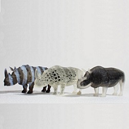
Our first result, as shown in Figure 5, highlights the ability to easily apply different fablets to the same base geometry. The appearance of the rhinos varies significantly, and each uses a variety of features in OpenFab. For instance, the left rhino uses displacement mapping in the surface phase of the fablet to create microspikes over the rhino’s skin. The volume phase of the fablet samples from a zebra-like texture to apply a layer of textured material near the surface. It uses the ability to query the nearest point to both retrieve the texture coordinate necessary to sample the texture and determine whether to apply the textured material. The center rhino has holes carved out throughout its body by returning void in the volume phase of the fablet. We use a distance function to separate the transparent outer shell of the rhino from the black inner core. The right rhino achieves its look in a similar fashion.

Figure 5. Three rhinos defined and printed using OpenFab. For each print, the same geometry was paired with a different fablet—a shader-like program that procedurally defines surface detail and material composition throughout the object volume. This produces three unique prints by using displacements, texture mapping, and continuous volumetric material variation as a function of distance from the surface.
Our next result, the butterfly (Figure 6), highlights the use of object priority to achieve a CSG difference-like operation. The butterfly is placed within a transparent casing to simulate an amber fossil (the butterfly geometry has higher priority than the casing). We procedurally define volumetric cloudiness and particles in order to increase the appearance realism of the amber.

Figure 6. Insect embedded in amber. Object priority is used to embed the procedurally displaced insect mesh inside the outer amber hemisphere. The amber region mixes small amounts of white material according to procedural noise to model cloudiness and variation in the amber.
The bunny and the teddy bear pair (Figure 7) demonstrate the ability to reuse the same fablet across different models. The material used to print these objects is flexible but volume preserving. The fablet introduces procedurally defined and repeated void spaces in order to achieve a compressible, foam-like material. This demonstrates the ability to easily define and apply patterned materials. One could also make the 2D or 3D pattern be texture-driven. OpenFab allows one to build a library of such fablets similar to how material and light libraries are built for image rendering.

Figure 7. A procedurally defined foam material makes the bunny and bear squishy. Color and squishiness vary procedurally over the models.
The magic postcard (Figure 2) demonstrates a creative use of texture-driven displacement mapping in its fablet (code in Section 4.4). The front face of the postcard (shown left) is textured using a foreground layer of image texture. The back of the postcard (shown right) displaces the surface to create a spatially varying transmission effect. The amplitude of the displacement at each point is driven by the luminance of the background image. When illuminated solely from the front, the background layer is not visible. When another illumination source is added from the back, the whole image becomes visible (shown center). Similar to other textured objects, the postcard fablet uses the nearest point query and distance from the surface to perform texture-driven material assignment.
The marble table in Figure 8 (center) procedurally recreates the appearance of marble. It uses Perlin noise15 to define a solid texture in the volume phase of the fablet. Note that the material distribution changes continuously to create a graded material.

Figure 8. Left: procedurally defined materials with anisotropic mechanical properties. Center: Marble-like material generated using Perlin noise. Right: Procedurally defined and fully parameterized aspherical microlens array with baffles.
The microlens in Figure 8 (right) demonstrates a working, procedurally defined microlens array. The surface phase of the fablet transforms a slab of material into an array of aspherical lenses by using displacement mapping. The volume phase of the fablet adds baffles in between the lenslets and assigns the two materials used (clear for lenses and black for the baffles). The baffles reduce the light leakage between the neighboring lenses.
Finally, in Figure 8 (left), we show two examples of objects made of procedurally defined materials with anisotropic mechanical properties. The core of the material is made of transparent and elastic material. We procedurally insert helical (top) or straight (bottom) rods made of white and rigid material. These rods influence the mechanical behavior: the helical rods allow twisting motion of the object in clockwise direction and very little twist in the opposite direction; the straight rods transform downward side pressure into transverse motion that causes elongation.
We ran a number of simulations to test the scalability of our initial implementation and its ability to provide fabrication data in real time to a 3D printer. Even without significant optimization, the initial OpenFab implementation meets our key design goals:
- Across many sizes of slices, it can stream the data as fast or faster than a high-end, multimaterial 3D printer can output material (in our case, an Objet Connex 500).
- Time to first slice output is seconds, even for models large enough to require hours to print.
- Memory footprint can be kept under a modest configurable threshold of 1.5GB without sacrificing these performance requirements.
Still, we observe that a significant amount of our runtime is spent in the nearest distance and nearest point queries and believe that a combination of optimized implementation of these and other key operations with data-parallel code generation could easily provide at least an order of magnitude performance increase to keep up with foreseeable future printers.
7. Discussion and Future Work
We have found the programmable pipeline abstraction a surprisingly powerful way to describe complex multimaterial 3D prints with a wide range of mechanical and optical properties. We think the OpenFab pipeline provides a solid and scalable foundation on which to build many multimaterial fabrication techniques.
The current programming model is powerful, but it is not the most natural way to describe all possible results. In the future, we think there is a great opportunity to spread proceduralism throughout the pipeline. Procedural geometry plugins could be more natural than the existing fablets for some types of geometry (e.g., synthesizing L systems) and would be complementary to the existing stages. Programmable dithering could also increase the flexibility of the pipeline and the degree of user control over the exact printed output.
Designing a full ecosystem around this pipeline is a natural direction for follow-up work. This could include a procedural modeling tool, a visual fablet authoring tool, and a print preview based on measured material properties. It is also desirable to extend the pipeline to integrate various mesh optimizations for automatic partitioning of large prints14 and automatic detection and correction of structural stability.18
Performance is another area of possible future work. Our current implementation is more than fast enough to keep up with current printers. But, as printers get faster, build volumes grow, and fablets become more complex, it will be important to improve performance. Fortunately, there is an enormous room for optimization and parallelization in our implementation. The nearest surface queries from the volume fablet phase are a major component of our programming model and the single most expensive operation in our implementation. There is an opportunity to make these queries more efficient. Further, it will be interesting to define more complex surface-volume attribute relationships, such as alternative attribute interpolation methods.
Finally, native backends for many types of printer hardware will be important to realizing the full potential of the OpenFab pipeline. OpenFab was designed from the outset to drive continuous material output at full printer resolution. Current commercial printer software, however, is limited to STL format input and fails when given more than a few million polygons. This significantly limits the scale of spatially varying output we can feed to current commercially available printers. The printer backends, however, take raw full-resolution bitmaps of each slice. Interacting with printers at the raster level will allow streaming prints of continuous material variation at much larger scale.
Given the high-frequency details in dithered multimaterial slices, implementing a backend for vector path 3D printers (e.g., FDM) remains a challenge. Recent work on “multiplexer” extruders that combine multiple filaments is promising, though. We imagine targeting such printers by using dither masks that map local dither patterns to linearly weighted combinations of the input filaments.
Acknowledgments
We would like to thank Jaakko Lehtinen and Mark Leone for providing seed code for our fixed-point rasterizer and OpenFL compiler, respectively; Mark Leone and Frédo Durand for extensive feedback on writing; Pitchaya Sitthi-Amorn for providing feedback during design discussions; and Ye Wang and Moira Forberg for helping produce our results. Steve Marschner provided helpful guidance during revision for Communications. Some models are from TurboSquid, and the Eiffel Tower photo was obtained through 123RF.
This work was funded in part by NSF grants CCF-1138967 and IIS-1116296, and DARPA grant #N66001-12-l-4242. K. Vidimče was supported by an NSF Graduate Research Fellowship and S. Wang by the MIT Undergraduate Research Opportunities Program.


Join the Discussion (0)
Become a Member or Sign In to Post a Comment