It is common to use computers to design shapes of physical objects such as furniture, but geometric modeling and the physical validity of shapes are conventionally considered independently. This makes creating aesthetically pleasing yet physically valid models challenging. In this paper, we propose an interactive design framework for the efficient and intuitive exploration of geometrically and physically valid shapes. During any geometric editing operation, the system continuously allows visualization of the valid range of the parameters being edited. When one or more constraints are violated following an operation, the system generates multiple suggestions involving both discrete and continuous changes to restore validity. Each suggestion is accompanied by an editing mode, which simultaneously adjusts multiple parameters in a coordinated manner to maintain validity. Thus, while the user focuses on the aesthetics of the design, our computational design framework helps to achieve physical realizability by providing active guidance to the user. We demonstrate our framework on plank-based furniture designs with nail-joints and frictional constraints. We use our system to design a range of examples, conduct a user study, and also fabricate a physical prototype to test its validity and usefulness.
1. Introduction
Recent advances in three-dimensional (3D) modeling systems (such as the appearance of Blender and SketchUp) have enabled novice users to design complex shapes, thus making content creation widely accessible. However, along with aesthetic appeal of the designed shapes, the physical properties are often very important, particularly if the resulting model is to be fabricated and used in the real world. For example, in the context of do-it-yourself (DIY) furniture design, various physical constraints must be satisfied. For example, a chair is only useful if it remains stable and does not break with the target load distribution. However, current modeling systems typically do not consider such physical plausibility in the design phase. This makes creating interesting shapes that also satisfy physical constraints difficult for novice users, who may not have specialist knowledge or relevant experience.
Geometric design and physical functionality are conventionally considered independently. The designer typically creates a 3D geometric shape that is then validated using a physical simulation, for example, a finite element method (FEM) solver. If the shape violates one or more physical constraints, it will be returned to the designer, who refines the shape. This process is repeated until a satisfactory design is found. Such a workflow may be undesirable for a number of reasons: the process is time consuming, essentially amounting to trial-and-error; it provides no guidance to the designer on how to rectify violations of the design constraints; and it encourages users to opt for standard shapes rather than to explore novel shapes.
For example, IKEA provides a range of design-at-home tools that are specialized for offices, kitchens, and bedrooms, and allow the user to define the dimensions of the room, interactively select 3D models from product catalogs, and place them in the room to create a layout. However, such systems only allow users to select from a list of preexisting objects. With the growing demand for customization, it is desirable for a system to allow users to change the shape of the furniture, while still being guaranteed that the objects remain functional, that is, will not, for example, collapse under target loads. Thus, our goal is to support such design exploration by providing real-time physical analysis.17,20,22 We investigate this in the context of nail-jointed furniture, with the aim of producing unusual and artistic shapes with non-standard inclinations, yet ensuring physical validity (see Figure 1).
A few advanced computer-aided design (CAD) systems (e.g., CATIA) support continuous feedback to check for validity. Similarly, Umetani et al.20 proposed an interactive system to provide real-time feedback on the physical constraints for garment simulations. Such methods, however, only inform the user whether or not the model is valid; they do not suggest how to restore validity. Whiting et al.21 reported a system to optimize procedurally generated buildings over a range of variables to produce a final model that is structurally stable. However, such an approach is not satisfactory for exploratory modeling as it neither provides creative support nor facilitates informed exploration of the design space.
We introduce a computational design framework for the efficient and intuitive exploration of valid shapes. Specifically, we actively guide the user to explore parts of the shape space that satisfy the constraints, thus relieving the user of the burden of ensuring realizability, via the following two modes: we analyze the current shape configuration and indicate the valid range of the parameter being edited; then we propose both continuous and discrete suggestions with coordinated editing modes to restore validity when the design becomes invalid. Note that, in contrast to a direct optimization-based solution, we leave the designer in control of form-finding by providing a visualization of the valid range with multiple deformation suggestions, as required, to guide the designer toward feasible geometric forms (see Figure 2).
In this work, we enable constrained modeling in the context of nail-jointed furniture design, while observing geometric and physical constraints. We consider three aspects: connectivity, that is, joint connections among planks are geometrically maintained; durability, that is, that the object does not fail at any of the joints under the target load distributions; and stability, that is, that the object does not topple or lose contact with the ground. The user interactively designs a shape model using standard modeling operations. In the background, the system continuously runs a rigid body simulation with frictional contact to provide realtime feedback on the structural validity of the design. The system uses a sensitivity analysis to describe how changes to the design affect the validity of the design.
We use this information to provide a range for the valid parameters being edited, as well as continuous suggestions to restore validity using a novel force space analysis approach. Each suggestion is accompanied by a coordinated editing mode that synchronously adjusts multiple components, which otherwise may be difficult for users to achieve manually, especially while satisfying multiple nonlinear constraints. Thus, the user can efficiently navigate the physically valid design space by following the ranges shown in the visualization and exploring the proposed suggestions (see Figures 1 and 14, the supplementary video and the executable demo).
The main contributions of this work are that we provide: (i) an interactive modeling framework for guided exploration of physically valid shapes, (ii) a design environment for nail-jointed, plank-based furniture, and (ii) a force space sensitivity analysis to generate design suggestions with continuous and discrete modifications to restore geometric and physical validity.
2. Exploring Physically Valid 3D Designs
Advances in geometric modeling have resulted in well-established CAD modeling tools. Exploratory design, however, remains challenging. This is mainly because mapping a partially formed design concept to a final 3D shape is ambiguous. Hence, researchers have proposed various frameworks for suggesting possible shapes to inspire and guide the user. Based on user-specified geometric relations across 3D components, Igarashi and Hughes7 generate a gallery of possible subsequent modeling operations to facilitate quick and intuitive modeling. In another influential work, Funkhouser et al.5 propose a data-driven modeling system in which the user provides the conceptual design using sketches, while the system suggests plausible geometric realizations by searching through a database of 3D models. Inspired by this philosophy, Chaudhuri and Koltun4 propose a data-driven system to compute and present components that can be added to the current design shape. The Insitu system12 provides spatial context by fusing data from multiple sources and combines them with image-billboarding to provide light-weight 3D environments for conceptual designs. In this work, we introduce a novel suggestive system for exploring shapes that are physically valid.
Given a 3D shape, state-of-the-art techniques can efficiently and accurately evaluate its physical validity. However, the inverse problem is less understood. In the context of animation, even small perturbations in initial parameters can lead to large changes in final configurations. Hence, Popović et al.14 propose a system to optimize parameters to satisfy user annotated keyframe specifications. In another interesting formulation, Twigg and James18 introduce backward steps to generate animations of rigid bodies with desired goal configurations. In this work, instead of motion parameters, we explore how shape changes affect the physical validity of a shape. We then use the information to interactively propose smart shape deformation modes.
 2.3. Interactive shape exploration
Immediate and meaningful feedback is essential in any design setting, especially in artistic exploration (see also Kerr and Pellacini8). Although such design spaces are often high dimensional, only low-dimensional subspaces are typically useful to intuitive exploration. In a data-driven setting, researchers have extracted low-dimensional embeddings (e.g., using mixture of Gaussian models) of desirable design spaces for appearance15 and for geometric modeling.17 Recently, Ovsjanikov et al.11 study variation patterns directly in appropriate descriptor spaces to extract low-dimensional deformation models on a representative template for exploration and navigation of collections of 3D models. In another approach, the deformation framework iWires6 demonstrates that direct preservation of inter- and intra- part relations using junction curves is effective for manipulating man-made models. More recently, Yang et al.22 propose a geometric framework to identify constrained modeling spaces where appropriate geometric properties in the form of algebraic constraints (e.g., planarity of quad faces) are preserved in the course of deformations and edits. Such exploration approaches, however, mostly focus on geometry, and physical validity considerations have so far been ignored.
Different optimization strategies have been proposed for various design problems: voxel selection and placements to create multiple target shadows,10 relief optimization for prescribed shadow footprints,1 furniture layout while increasing functional considerations such as accessibility,9, 23 or optimizing combinations of materials to reach target deformation behavior.3 In the context of buildings, Smith et al.16 model truss structures by structural optimization, while Whiting et al.21 optimize free variables in the context of procedural modeling with regards to structural feasibility by ensuring non-negative force between brick elements. These approaches propose final optimized shapes, which are not beneficial in initial exploratory stages. Instead, we introduce shape space investigation to understand the effect of geometric changes on physical validity and use the findings to expose the valid and useful parts of the shape space as suggestion modes (see also Yang et al.22).
3. System Overview
Figure 3-left shows our modeling interface, which consists of a modeling panel and a suggestion panel. The modeling panel basically works as a standard modeling system (e.g., Google SketchUp), although it is specialized for models consisting of multiple planks connected by nail joints. Our system continuously checks for validity in the background and shows whether or not the configuration satisfies geometric and physical requirements. Specifically, the system examines connectivity, durability, and stability. Note that we do not check for self-intersections at runtime. The result of the analysis appears as an annotation in the main panel during mouse dragging. Further, we provide suggestions in the suggestion panel after mouse release if the current shape is invalid. Suggestions, when selected, appear in the modeling panel.
Figure 3-right shows the basic modeling operations supported by our system. The user draws two 2D lines on the screen to specify a new rectangular plank (a–c) of predefined thickness (12 mm in our setting). The first line is drawn by mouse dragging and is placed on a selected plank. The end point of the first line becomes the starting point of the second line and its end point is indicated by a mouse click. The second line is either projected to an existing plank or aligned to the canonical xyz-coordinate system. We automatically generate a joint between the newly created plank and the existing planks on which the first and second lines are placed. The user can translate, rotate, and scale a plank using 3D widgets (d–f). When an edge of a plank is placed near another plank, these planks are automatically connected (g). Finally, the user places a weight by clicking on a plank in the weight mode (h). Note that the exact placement location of the weight on the selected plank is not important.
3.3. Validity visualization and suggestions
In Figure 4, we show the different scenarios when the current configuration becomes invalid. (a) When a joint becomes disconnected, the system highlights the joint in red. (b) When the model breaks at a joint, the system also highlights the joint in red. (c) When the model falls down, the system shows a red arrow. These warnings automatically appear and are continuously updated as the user interacts with the design, so that the user can move back to a valid state by direct manipulation based on the feedback.
In addition to checking whether or not the current configuration is valid, the system computes the valid range of the parameter (degrees of freedom, DOF) being manipulated and shows it to the user during direct manipulation (mouse drag). When the current configuration is valid, the system shows the valid range in black. When the current configuration is invalid, the system shows the valid range in red (see Figure 5). Explicitly showing the valid range reduces the need for trial and errors to stay within or return to a valid state during direct manipulation editing.
When necessary, after each mouse release, the system provides suggestions (capped to a maximum of 8 in our setting) on how to resolve an invalid state. When a joint becomes disconnected, the system shows how to reconnect it (Figure 6a). When the model is non-durable or unstable, the system shows how to make it durable and stable (Figure 6b and c). Each suggestion consists of a representative configuration and an optional coordinated edit mode. When the user clicks on a suggestion, the representative configuration appears in the modeling panel together with arrow marks indicating the coordinated edits (Figure 7a). The user drags one of these arrows to make coordinated editing, thus allowing the user to control multiple DOFs of a model simultaneously while satisfying the required constraints. These multiple DOFs are coupled together, that is, the user cannot fix the non-durability or instability moving each DOF individually. For example, in Figure 7, if the user slides the top board of the table toward the left, the angle of the left leg becomes perpendicular to the ground to compensate for the increase of the bending force on the left joint (Figure 7b and c).
4. Algorithm Overview
As the user edits the model (i.e., adds, removes, translates, rotates, or scales objects), we first attempt to restore the geometric constraints (i.e., joint connectivity and ground contact) by adjusting the length of the other objects. If this fails to satisfy the geometric constraints, we suggest discrete changes to fix the design. Once the model is made to satisfy the geometric constraints, we check the physical validity of the current shape and present the results to the user. We test for durability and stability, which amounts to checking for inequality constraints at joints and contact forces, respectively. In addition to indicating whether the design is valid or not, we analyze how the validity changes with respect to further geometric modifications, that is, what changes make an invalid model valid, and vice versa. The results of this analysis are used to compute valid ranges and make suggestions. Section 5 describes how we measure and analyze the physical validity, and Section 6 describes how we compute the valid ranges and make suggestions based on this analysis.
5. Physical Validity
In our interactive framework, we continuously analyze the current design to provide feedback to the user as to the physical validity of the current shape during editing. Specifically, the system checks for two kinds of physical validity: (i) whether or not the nail joint is durable and (ii) whether or not the structure is stable. In this section, we describe how to compute joint and contact forces and how to measure joint durability.
In any nail-jointed wooden structure, the joints form the weakest links, that is, such structures typically fail at the joints.13 For this reason, in our framework we model component planks of wooden furniture as assemblies of unbreakable rigid bodies, focusing on the joint and the contact forces.
5.1. Forces on a joint and contact point
We assume static equilibrium. Under this assumption, all of the forces in a rigid plank should be balanced and, therefore, the sum of rotational moments and the sum of linear moments will both be zero. Furthermore, the nail-joints should connect two planks rigidly, hence the relative position of any two planks is constrained such that their translation and rotation will be the same. We consider a further constraint in that the predefined contact points do not penetrate the floor. We determine the static equilibrium of the rigid plank by solving for static energy minimization under these constraints. Then we arrive at the translation ht and the bending force hr at each joint, and the contact force fcont at each contact point.
With the translation ht and the bending force hr at each joint, we check for durability of the nail-joints in response to the given forces. The mechanical properties of nails are well known, and have long been standardized with precise specifications in terms of the load-bearing capacity (see Bergman2). At each joint, there are two loads on the nails: (i) a pulling force, which acts along the axis of the nail, and (ii) a shearing force, which acts perpendicular to the axis of the nail. We represent these forces h (i.e., ht and hr) in a local coordinate system, where hn is the component normal to the joint face of plank Pj, hx is the component along the normal of plank Pi, and the remaining component is hy (see Figure 8). Each component of hr denotes the torque to twist the plank Pj with an axis of rotation in each direction. We assume the thickness of the plank is less than the width of the joint between Pi and Pj. Hence, the bending force hy determines whether the joint will fail. In Figure 8, we show how the force that pulls the nail from the joint arises from the bending force hyr. The joint forms a lever where the length of the lever arm is 0.5lz; the pulling force is given by

where lz represents the thickness of the plank (12 mm in our tests) and Nnail denotes the number of nails in joint Nij. The shear force is then given by

We determine a joint to be durable if both forces are within allowable threshold margins.2 Please see Umetani et al.19 for further details.
6. Exploration of Valid Spaces
If the current design is valid, we indicate the range of user manipulations that maintain design validity. If the current design becomes invalid, we make multiple suggestions to restore validity. Note that, even though the (unconstrained) configuration space has a large number of dimensions, our framework only exposes meaningful (i.e., valid) suggestions, thus greatly simplifying the task for the user. We make both continuous and discrete suggestions: while continuous suggestions leave the inter-plank joint topology unchanged, discrete suggestions involve adding support materials.
Aside from the physical validity of our system’s shapes, that is, durability and stability, shapes are geometrically restricted by two further constraints: (i) geometrical joint constraints and (ii) contact constraints (see Section 5). We first restrict the design space so that the shape satisfies these geometrical constraints, and then investigate the physical validity. Each plank has 8 DOFs in the design: three for translation, three for rotation, and two for edge lengths around the plank faces (the plank thickness is fixed). For each DOF, we ensure that the contact constraints and joint constraints are satisfied by adjusting the length of the planks (Figure 9-left). Furthermore, some DOFs may be invalid, for example, if both ends of a plank are nailed, the plank length cannot be adjusted (see Figure 9-right). We identify and remove such invalid DOFs from the design space. Note that if there are C plank components and #DOFinvalid invalid design DOFs, the constrained design space Γ has dimensionality of Nγ: = 8C – #DOFinvalid. Each basis corresponds to one translation, rotation, or change in length of a given plank and/or adjacent plank. We scale the translation and length change bases inversely with the edge length of the maximum bounding box to make the DOFs for translation and changes in length dimensionless, as is the case for rotational DOFs. Then we enable an exploration of a physically valid subspace of a constrained design space Γ.
Recall that a shape is physically valid if two conditions are satisfied: (i) the shape is durable, which amounts to each joint with both pulling and shear forces below allowed thresholds, which is formalized as

and (ii) the shape is stable (i.e., it does not topple), which amounts to each contact point with a non-negative contact force fcont in the direction normal to the ground, that is,

Let the corresponding subspaces of the configuration space Γ be Γdurable and Γstable. Thus, the valid shape space is Γvalid := Γdurable ∩ Γstable. When the current design becomes invalid, the goal is to provide multiple suggestions to return to the valid shape space (see Figure 10).
The valid space typically has a complex boundary since it is characterized by nonlinear inequality constraints. Furthermore, because the configuration space has a larger number of dimensions, computing exact boundaries is difficult and time-consuming. In addition, it is almost impossible to arbitrarily pick a valid shape directly from the high-dimensional space Γvalid. Instead, we first pick several meaningful search directions to pursue, that is, directions whereby the invalid shape becomes valid under relatively small manipulations. For each such direction in the design space, we use a line search to identify configuration intervals where all of the validity conditions are satisfied.
Because the boundaries of Γdurable and Γstable are characterized by force inequalities, we consider the valid shape space boundary in the force space, that is, a coordinate space with forces as the axes. This simplifies the problem as the boundary is then geometrically prescribed by the corresponding inequality. For example, with two contact points, the stable region is 2D and Equation (4) simply indicates that the first quadrant is in the stable region (see Figure 10).
To efficiently characterize the force space describing joint durability, we make two approximations: (i) the translation force ht in Equation (1) remains constant with small design changes and only the bending force hr varies, and (ii) the shearing force in Equation (2) does not change with small design changes. These approximations are good when the bending force hr is dominant, and the design is more sensitive to hr than ht in response to changes in the design. Thus, Equation (3) becomes

Geometrically, the stable region Γstable can be approximated as a high-dimensional, axis-aligned cuboid with edge lengths of Λmax and centered at the origin in the joint bending force space.
Note that the number of dimensions of both the contact force space and of the bending force space are smaller than that of the configuration space (|Γ| ≈ 8C). In particular, the contact force space has the same number of dimensions as the number of contact points, and the joint bending space has the same number of dimensions as the number of joints Nij. Next we describe how to efficiently search for directions in this simplified representation. We denote the boundaries of the stable and durable force space as
 and
and
 , respectively.
6.3. Visualization of the valid range
During direct editing, we display the valid range of the parameter being manipulated. To do this, we evaluate the validity by changing the parameter. If the current configuration is already valid, the search proceeds in both directions until it becomes invalid to identify the bounds. If the current configuration is invalid, we first select the direction of the search using the results of the sensitivity analysis, and then run a bisection search along that direction to identify the valid range; this is described in the following subsection.
6.4. Continuous shape suggestions
When the current configuration becomes invalid, we compute several suggested configurations: (i) if only stability is violated, the system finds designs to restore stability by analyzing the boundary of
; (ii) if only durability is violated, the system finds designs to restore durability by analyzing the boundary of
; and (iii) if both stability and durability are violated, the system first proposes designs to restore stability, and then to restore durability.
To generate valid suggestions, we first assume forces vary linearly as a function of the changes to the design, and find candidate suggestions. Then we run a physics simulation using the nonlinear constraints to compute whether the designs are valid. Figure 11 shows a sample comparison with and without the linear approximation. If we cannot find valid shapes in this direction, we simply omit it from the suggestions.
Simultaneous exploration of the full design space (|Γ| ≈ 8C dimensions) is impractical for real-time performance. In addition, users may find suggestions that involve variation in many parts to be confusing and not helpful. Instead, we restrict suggestions to at most M DOF for any suggestion, where M = 3 in the examples described here. We try all possible combinations by selecting m design DOFs (where m ≤ M), denoted by {γ1, …, γm}. We parameterize the changes to the design to make the candidates into a vector s ∈ Rm, where s: = Σmi=1 Si γi.
Durability-restoring candidates. A desirable change to the design s should quickly make the design durable. Thus, we find a design change s such that the joint bending forces are in the valid region
, while ensuring that the change is small:

where matrix
 encodes the sensitivities of the joint forces with respect to design changes, that is, K0 := ∇γ hry evaluated with the current joint bending force hry0. For the real-time performance necessary for an interactive software application, we restrict s so that the changes are in the direction which makes the norm of the bending forces as small as possible. We use a bruteforce method, whereby all possible M! combinations in the configuration space are explored, taking advantage of the simple axis-aligned cuboid approximation of the durable region. Solving Equation (6) can be seen as detecting collisions of rays with the durability cuboid where a ray is in the search direction and has a origin at hry0. We accelerate the search by culling any direction if either the norm of the sensitivity |K0| is small (≤ 1 in our tests) or the ray is in the direction away from the cuboid.
Stability-restoring candidates. We compute stable shape suggestions in a similar manner to the durability case. Specifically,

and where
 is a sensitivity matrix of the contact forces with respect to design changes, that is, L0 := ∇γ fcont evaluated at the location of the current contact force fcont0. The candidates are generated in the same manner as with durability restoration. Figure 12 shows some typical examples.
6.5. Discrete shape suggestions
If the structure is not durable, we try to make it durable by adding a support plank as a reinforcement around a joint that is under excessive force. Typically, nail joints connect two planks that are nearly at right angles, making it difficult to attach supports between the planks that are connected by joints that are not durable. Instead, we try to connect two planks that are parallel and place a supporting plank so that it is orthogonal to the other two planks. We do this using a greedy strategy. First, we choose a combination of two planks Pi, Pj such that (i) they are nearly parallel (we use |ni · ni| < 0.5 where, ni is the face normal of the plank Pi, and nj is the face normal of the plank Pj); (ii) there is a third plank Pk between the two planks, which is connected to Pi and Pj using nail joints; and (iii) one or both joints Nik and Njk are not durable. We suggest adding support material between Pi and Pj at a location chosen from several (rule-based) candidate positions so that the support does not intersect with any of the existing planks (see Umetani et al.19 for further details). We check for durability of the joint by running a physical simulation to ensure that the supporting plank is effective. The system attempts numerous combinations of planks until it finds effective supporting planks based on standard rules used in woodwork.2 There is scope here for the use of more complex strategies, which may form part of future work.
7. Results
In our system, we consider furniture designs using 12 mm-thick medium density fiberboard (MDF) with 32 mm-long nails, spaced at interval of 20 mm. Such a placement can take a maximum shear force of fshear max = 190 N and maximum pulling force of fpull max = 3.5 kN/m.13 We set the coefficient of static friction to 0.5. In our current implementation, we can handle 10 to 15-plank designs with sufficient speed for interactive design. In each exploration session, the user progressively adds planks and proposes an initial configuration along with the target load-bearing capacity. For example, in Figure 2, we place a 50 kg weight on the horizontal plank and a 15 kg weight on the supporting back plank. The final design was found following several iterations of suggestions and exploration of the design space. We built a physical prototype (where the construction took around 4 h) and found it to behave satisfactorily under the target load (see the supplementary video on the project page).
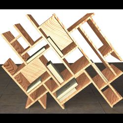
In Figure 13, we use our system to design non-conventional bookshelves. The computational support is critical, as we have little intuition in such unusual situations and cannot benefit from prior experience. Guided exploration helps the user to explore the design limits while not having to consider physical validity.
Figure 14 shows additional design sessions with our system. Note that we show only a few representative suggestions; we refer the reader to the supplementary video and demo for further details. The user is provided with corrective suggestions only when the design becomes invalid. Furthermore, each suggestion comes with a range whereby the designed shape remains valid. Thus, even when the suggestions involve multiple planks, the user only has to adjust a single parameter along the suggested deformation direction. For example, with chair 1, we show three different suggestions, each involving a pair of planks to be simultaneously manipulated to restore validity. In the case of chair 2, the situation is similar, except we have three specified weights.
In the case of shelf 1, note that the geometry of the initial and final configurations is similar. However, it is non-trivial to determine the validity-restoring path using trial-and-error, particularly since there are different interactions involving simultaneous rotation and anisotropic scaling of multiple components. In the case of shelf 2, the top and the large side planks are adjusted multiple times over the course of the guided exploration to result in a shape that can withstand the three vertical loads. Note that the complexity of the configuration space rapidly grows with the number of planks, making it increasingly difficult to design valid shapes manually without computational support and guidance. Table 1 lists typical continuous and discrete times for generating suggestions. To generate suggestions, we must explore O(N3γ) directions in real time, even for 15–20 planks using a linear approximation, with the line search step accounting for the majority of the computational time. We recall that each additional plank results in an increase in Nγ of roughly 8 (see Section 6.1).
User study. We carried out a user study to obtain feedback from the participants. Recreating a typical design scenario, we asked the user to design a piece of furniture freely, following a concept of their own. Nine test users (all novice designers, computer science graduates, and with one female user) designed furniture with three types of system: (i) one without feedback from the physical simulation (i.e., the participants were not informed as to which joints were durable or whether or not the furniture was stable); (ii) one with feedback from the simulation (validity check and valid range visualization) but without suggestions; and (iii) one with feedback and suggestions (i.e., the system described here). While using system (i), the user was able to see the results of the simulation up to five times whenever they liked, assuming the use of conventional shape-modeling software along with simulation software. Each participant began by creating a concept design on paper. Then the participant created 3D furniture models with the three systems to realize their concept design. To counterbalance learning effects, we separated the nine participants into two groups: five participants used the system in the order (i, ii, iii), while the remainder used the system in the reverse order (i.e., iii, ii, i). On average, the participants took roughly 30 min per successful design.
In Figure 15, we show a session where the participant, who was proficient at using Google SketchUp, used the systems in order (i, ii, iii). The participant simply failed to design a valid shape using system (i). With system (ii), he managed to design a valid piece of furniture, but complained that the shape of the furniture was boring and far from his initial design concept. Using system (iii), he successfully designed a valid piece of furniture closely following his initial concept. Other participants fared similarly. All nine participants successfully created valid pieces of furniture that were close to their initial concepts using our system. Note that even the participants that used the system in the reverse order (iii, ii, i) mostly failed to recreate their initial design using systems (i) or (ii), although they did achieve successful designs using system (iii). The validity-restoring suggestions often involve synchronous editing of multiple parts, which is challenging without suitable computational support. One participant commented that displaying the range of edits was very useful for fine-tuning a design.
8. Conclusion and Future Work
We have described an interactive computational design framework for guided exploration of physically valid shapes for nail-jointed furniture. Our system provides active realtime guidance to help users avoid invalid designs, due to either stability violations or excessive joint forces. We use a novel force space analysis for both bending forces and contact constraints to generate multiple suggestions, along with respective valid deformation ranges, involving continuous and discrete geometric changes.
We have identified a number of directions for future work. These are summarized here. Better stress modeling: we modeled each plank as an unbreakable rigid body; however, to handle flexible planks, it is desirable to accurately model the internal stresses. Designing dynamic objects: designs with multiple possible configurations, such as a rocking chair, require an extension of our method; one approach is to treat the problem as a coupled guided exploration with multiple target configurations. Scalability: exploring valid designs involving a large number of components is difficult in our system; a possible solution is to reduce the number of DOFs by exploiting the structure and redundancy of the input models and exploring a hierarchical solution space.
Acknowledgements
We thank Lars Hesselgren, Helmut Pottmann, Anthony Steed, and Michael Wand for their comments and useful suggestions. The work was supported in part by a KAUST visiting student grant, the Marie Curie Career Integration Grant 303541, the ERC Starting grant SmartGeometry (StG-2013-335373), JST, and JSPS.
Figures
 Figure 1. Modeling a design concept (a) often produces invalid 3D realizations (b) due to model instability (i.e., toppling) or non-durability (i.e., excessive joint forces) under target loads. Our interactive computational design framework supports guided shape exploration to help the user reach a valid configuration, which then can be readily manufactured (c).
 Figure 2. Given physically invalid designs due to model instability (i.e., toppling) (a) or non-durability (i.e., excessive joint force) (c), we propose design suggestions (b, d) to restore physical validity. The suggestions provide guided shape space exploration to the user, who can quickly realize valid nail-jointed furniture designs under target weight-bearing and practical material specifications (e, f).
 Figure 3. (Left) The modeling interface consists of the modeling and the suggestion panels. (Right) The modeling interface with typical stages shown: creation (a-c), translation (d), rotation (e), scaling (f), and connection (g), along with placing a weight (h).
 Figure 4. Different warnings flagged by our system for invalid configurations: joints get disconnected (a), a model becomes non-durable due to excessive force on the nails (b), or it becomes unstable, that is, topples (c).
 Figure 5. Range indicators. Range is shown in black when the current configuration is valid and in red when invalid.
 Figure 6. Example of suggestions. A joint is connected (a), the model is made durable (b), or the model is made stable (c).
 Figure 7. Example of coordinated editing using suggestions. The table is non-durable and the system gives multiple suggestions (a). The user clicks on a suggestion and it appears in the modeling window (b). The user can change the position of the top board and left leg simultaneously by dragging any of the arrow handles (c).
 Figure 8. (Left) Decomposition of a constraint force into components in the local coordinate system. (Right) The rotational force leads to a force that pulls the nail, which can affect the durability of the joint.
 Figure 9. Constrained design modes: (a) the lengths of neighboring planks of the edited planks are adjusted so that joints stay connected; (b) a translation mode is invalid if both ends of the planks are jointed.
 Figure 10. A shape is valid if it is both stable and durable. For invalid shapes, we propose deformation suggestions to return to the valid part of the shape space. We work in force spaces defined by the contact and bending forces for stability and durability, thus simplifying the problem. Specifically, stability amounts to contact forces being restricted to the first quadrant, while durability amounts to bending forces being restricted to a durability rectangle. Note that, although in this example the force spaces are two-dimensional (2D), in general we work in higher-dimensional spaces.
 Figure 11. Comparison of a stable shapes and a durable space with and without the linear approximation.
 Figure 12. Stability-restoring suggestions.
 Figure 13. Designing non-standard furniture is difficult for novice users. Our guided exploration framework allows users to design furniture with strange configurations easily.
 Figure 14. Typical nail-jointed furniture design sessions in our guided exploration framework. Only a few suggestions are shown in each example. Please refer to the accompanying video and demo for further details. Note that suggestions often involve synchronous manipulation of multiple planks, which is difficult to achieve without computational support.
 Figure 15. Starting from a design concept (bottom-left), three failed attempts with no feedback or suggestions (i1–3), using only feedback without suggestions (ii), and using our system (iii).


Join the Discussion (0)
Become a Member or Sign In to Post a Comment